What has four legs but only one eye? A teapot of course!
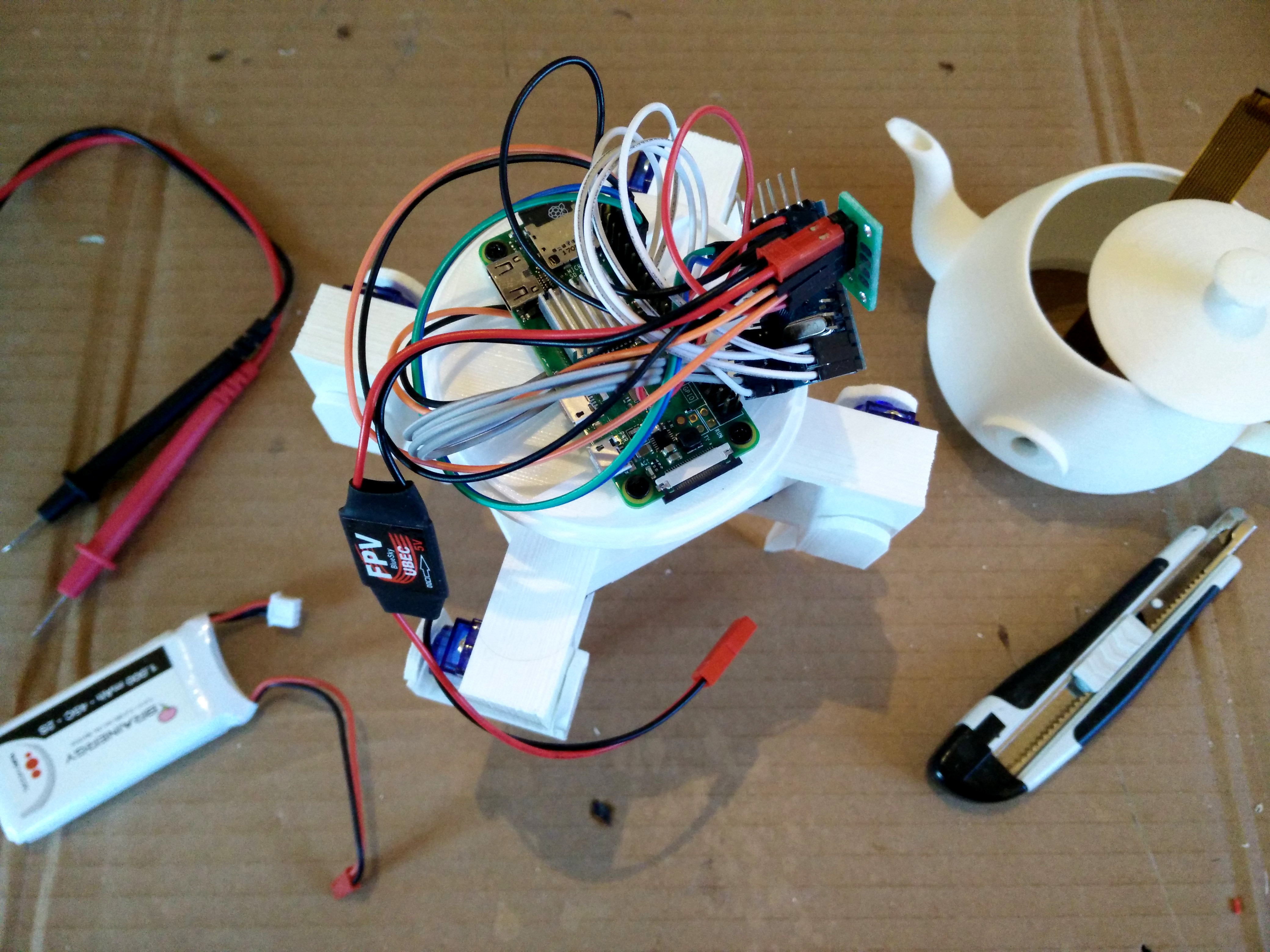
My new robot is based on a Raspberry Pi Zero W with a camera. It is connected via a serial link to an Arduino Pro Mini board, which drives servos. Since each one of the four legs will have two articulations, each with one servo, we need eight servos in total.
Here is a list of the material we will use:
- a Raspberry Pi Zero W
- a Raspberry Pi camera module V2
- a camera adapter for the Raspberry Pi Zero
- an Arduino Pro Mini 3.3V/8MHz
- 8 micro servos 9g rated ~5V (Tower Pro SG90 or similar)
- a 5V switching regulator rated at least 3A
- a 2S LiPo battery, 1000mAh is good
- a MicroSD card for the Raspberry Pi, 16GB is good
- a USB to UART bridge to program the Arduino board
- Dupont wires, screws, pins, prototype board, soldering material, and glue
Let's start by designing and printing the parts. I use OpenSCAD, and print with white PLA, as usual.
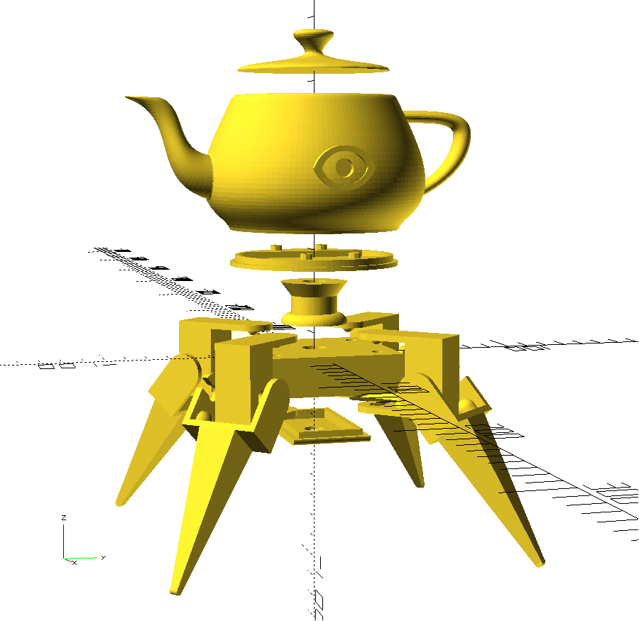
View of the 3D models set
You can download the SCAD source files (licensed under GPLv3) and the corresponding STL files here or on my GitHub repository. The models are also available on Thingiverse.
If you have played the videogame Alice: Madness Returns, you might have recognized one of the ennemies as source of inspiration. The shape and the number of legs are different, but still, it's basically a teapot with a single eye on legs! You might also have recognized the famous Utah teapot, that I already used for my dancing teapot.

Screenshot from Alice: Madness Returns showing the Eyepot
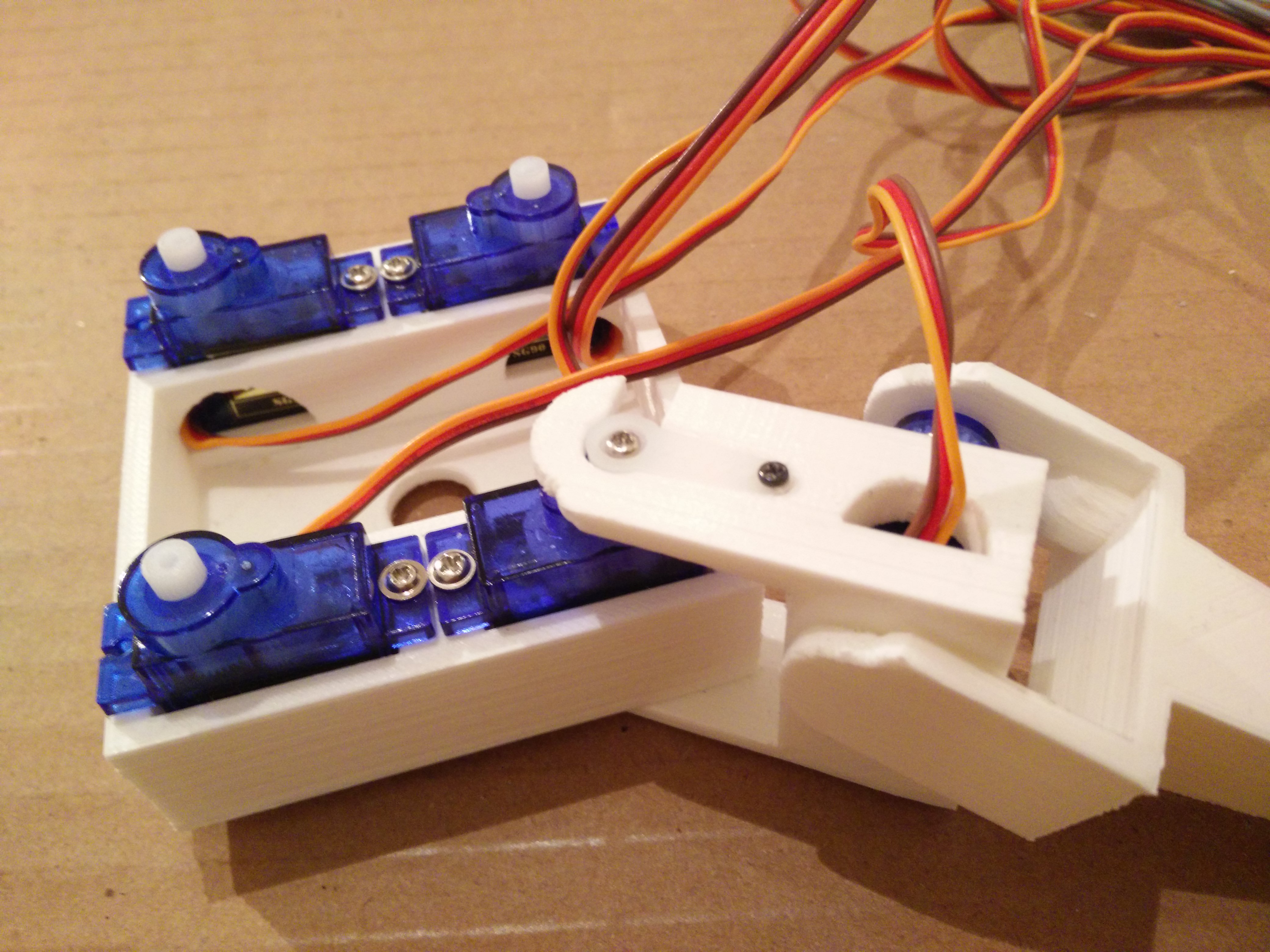
Once everything is printed, let's assemble the robot! The legs have two articulations each: the knee rotates horizontally and the ankle rotates vertically.

A leg with the knee servo mounted
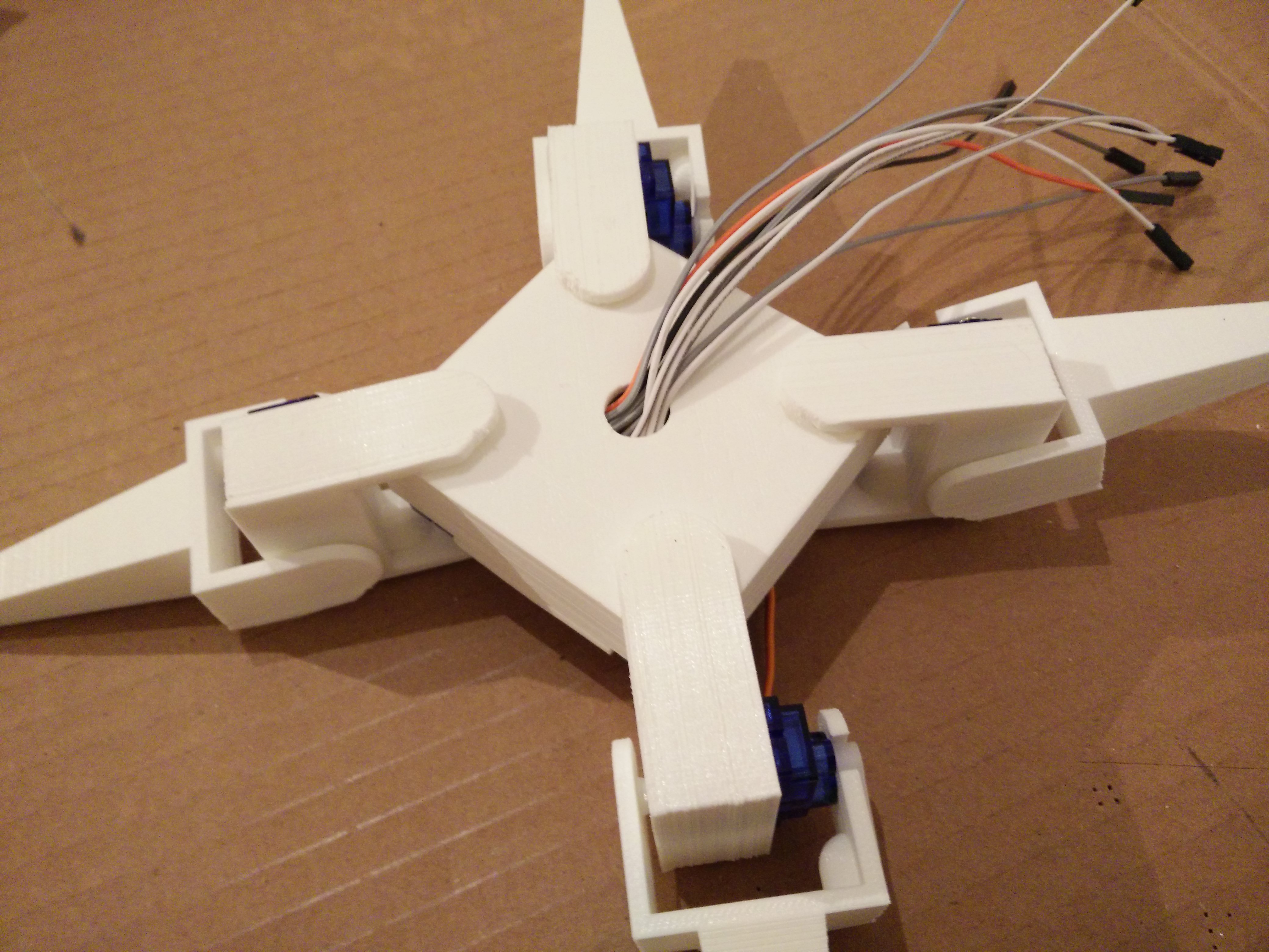
The platform hosts the four ankle servos. The compartment in the center will host the distribution board connecting the eight servos. A nice tip when dealing with servos: don't screw the arms at first, wait for them to be connected, so you can first drive them to neutral position, then tighten the screws.
The platform with the four ankle servos mounted and a leg attached
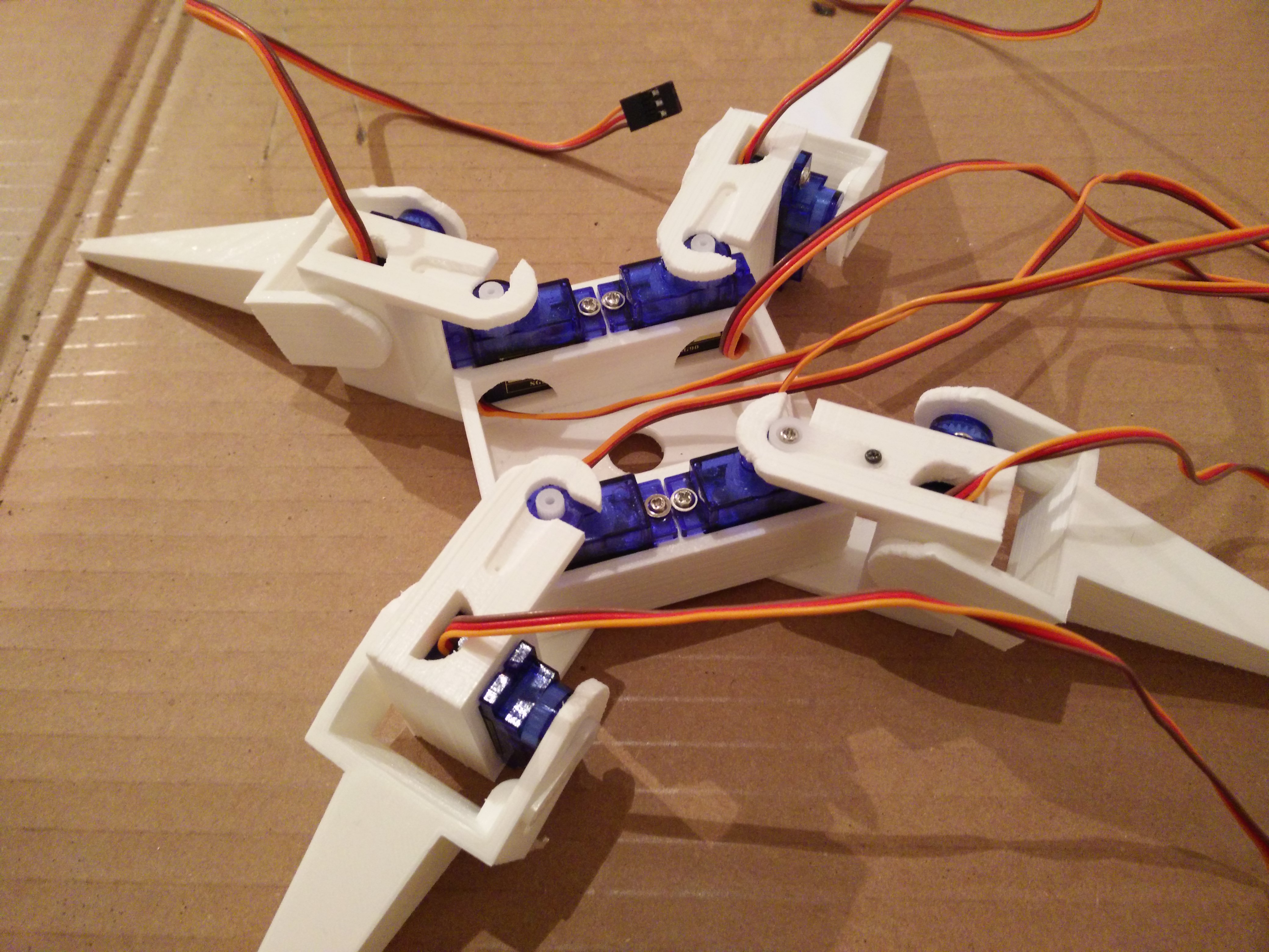
The platform with the four legs attached
With a piece of prototype board sawn to the correct dimensions and pins, I made a distribution board to connect the eight servos. The pins are welded together on the back of the board, so each servo is connected to the power line, the ground line and an indivial control wire. Ten wires go out to the head: one for the power, one for the ground, and the eight control wires that allow to drive each servo.
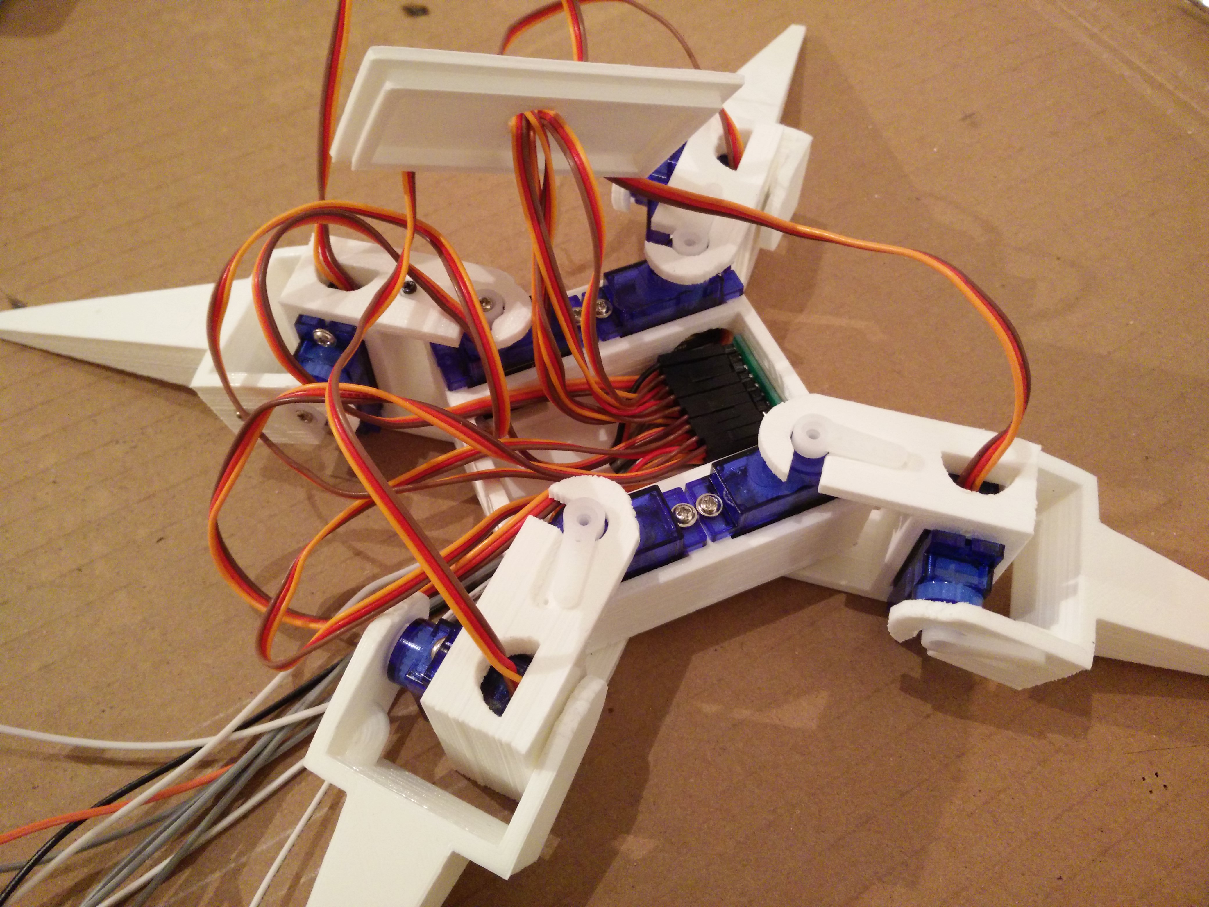
The servos connected to the distribution board
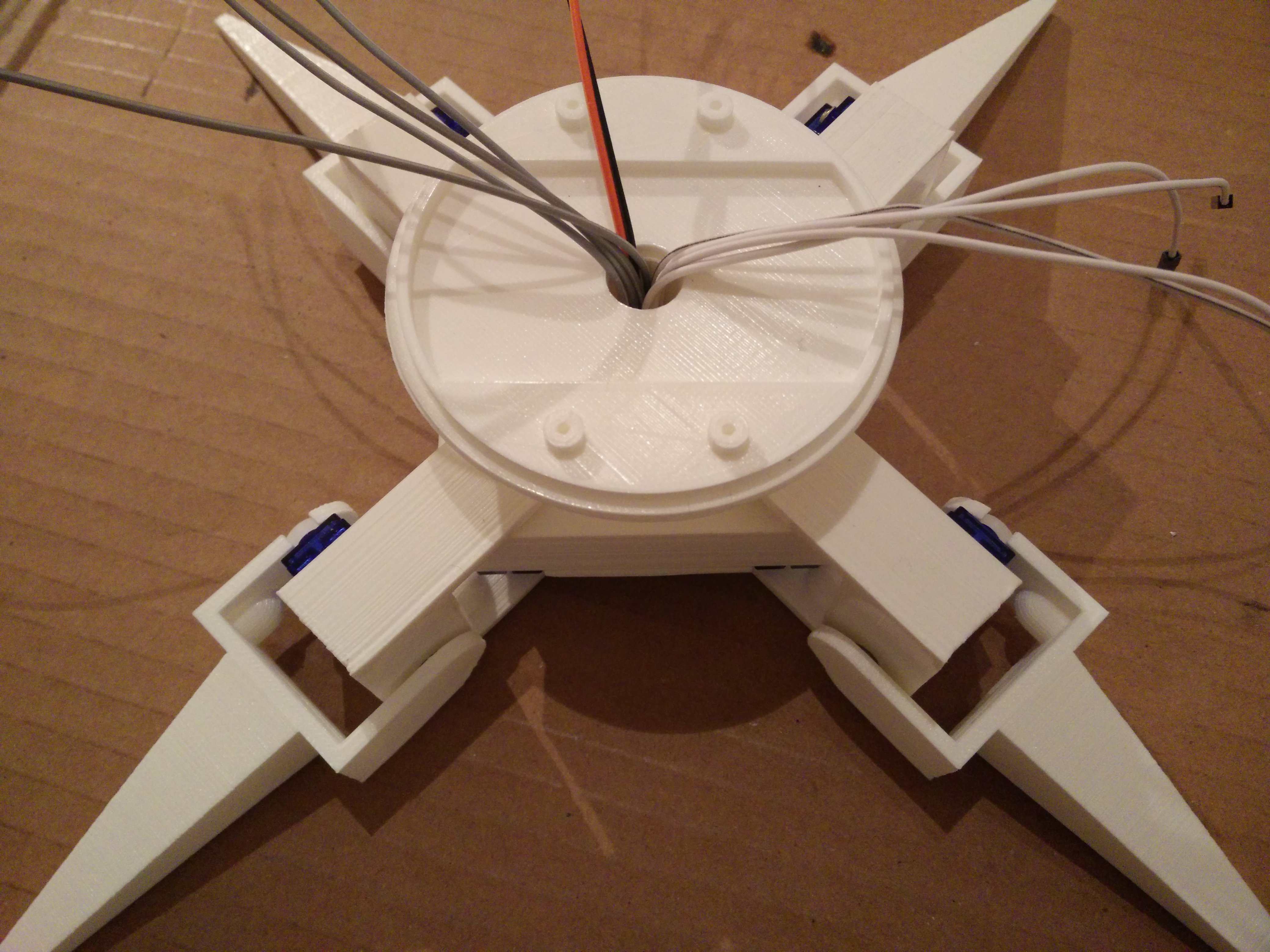
The power, ground and control wires go through the neck of the robot to be connected in the teapot-shaped head.
Power, ground and controls wires for servos going out on the top
The neck cannot move and is simply glued to the platform on the bottom and to the teapot base on the top. Its central hole allows the wires to go through to the head.

The neck is glued to the platform with wires going through
The base of the head is glued on the neck with wires going through
We can now connect the servos wires. For power and ground, I made a small distribution board to connect the dupont wires cleanly. The 2S LiPo battery 7.4V tension (actually from 8.4V at full charge to 7V) is regulated to 5V with a switching regulator (aka UBEC). Since I chose to have the servos powered by the regulated 5V tension, we need to dimension the UBEC correctly: each 9g servo draws roughly 250mA when rotating (even potentially up to 600mA when stalling), the Pi Zero W draws up to 250mA with video capture and Wifi enabled, while the Arduino Pro Mini draws only around 5mA. Therefore, 3A is a minimun rating here.
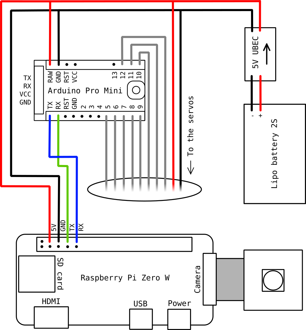
Schematic of the connections between components
There is a bit of subtlety when connecting the Arduino Pro Mini: since it is the 3.3V version, we connect the 5V input to RAW. If it was 5V, we would connect directly the 5V input to VCC, because else you would get less than 5V in the board due to dropout in the regulator.

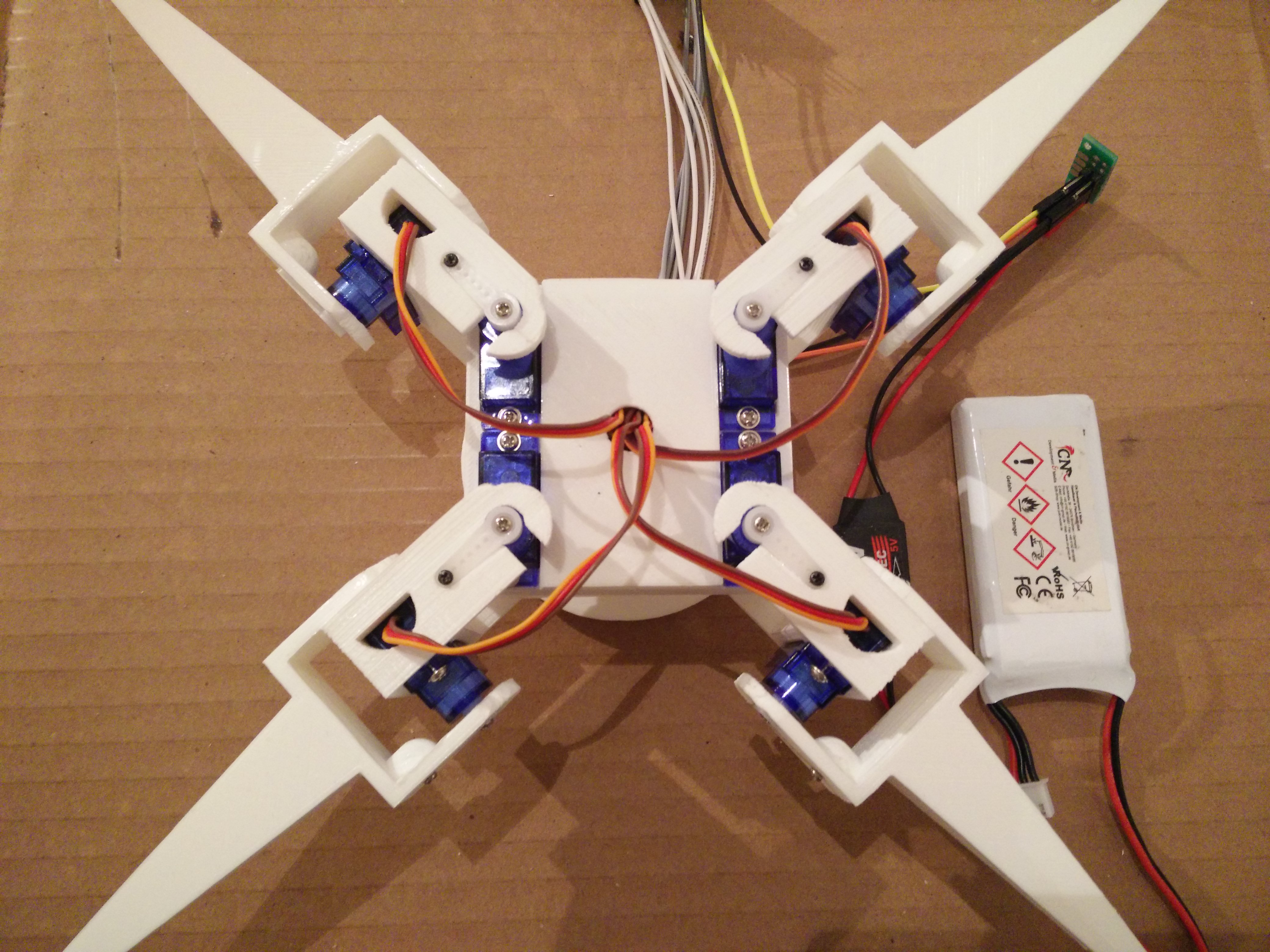
Arduino Pro Mini board and battery connected to servos
Now is a good time to set the servos to the mean angle (90 degrees) from a dummy Arduino program, and then tighten the screws with the arms in middle position. After we checked everything is working properly with the servos, we can clip the bottom cover.
Bottom view with cover closed
The camera support is glued inside the teapot-shaped top part of the head. It allow to secure the Raspberry Pi camera in the eye with a pair of screws.

The camera positionned inside the top of the head
The Raspberry Pi Zero W is screwed on the base of the head. The servos wires have space to fit below the board.
Everything is connected, the top of the head is ready to be mounted
Finally, we clip the teapot-shaped to of the head, without forgetting to connect the camera first, and close the teapot with its cover.
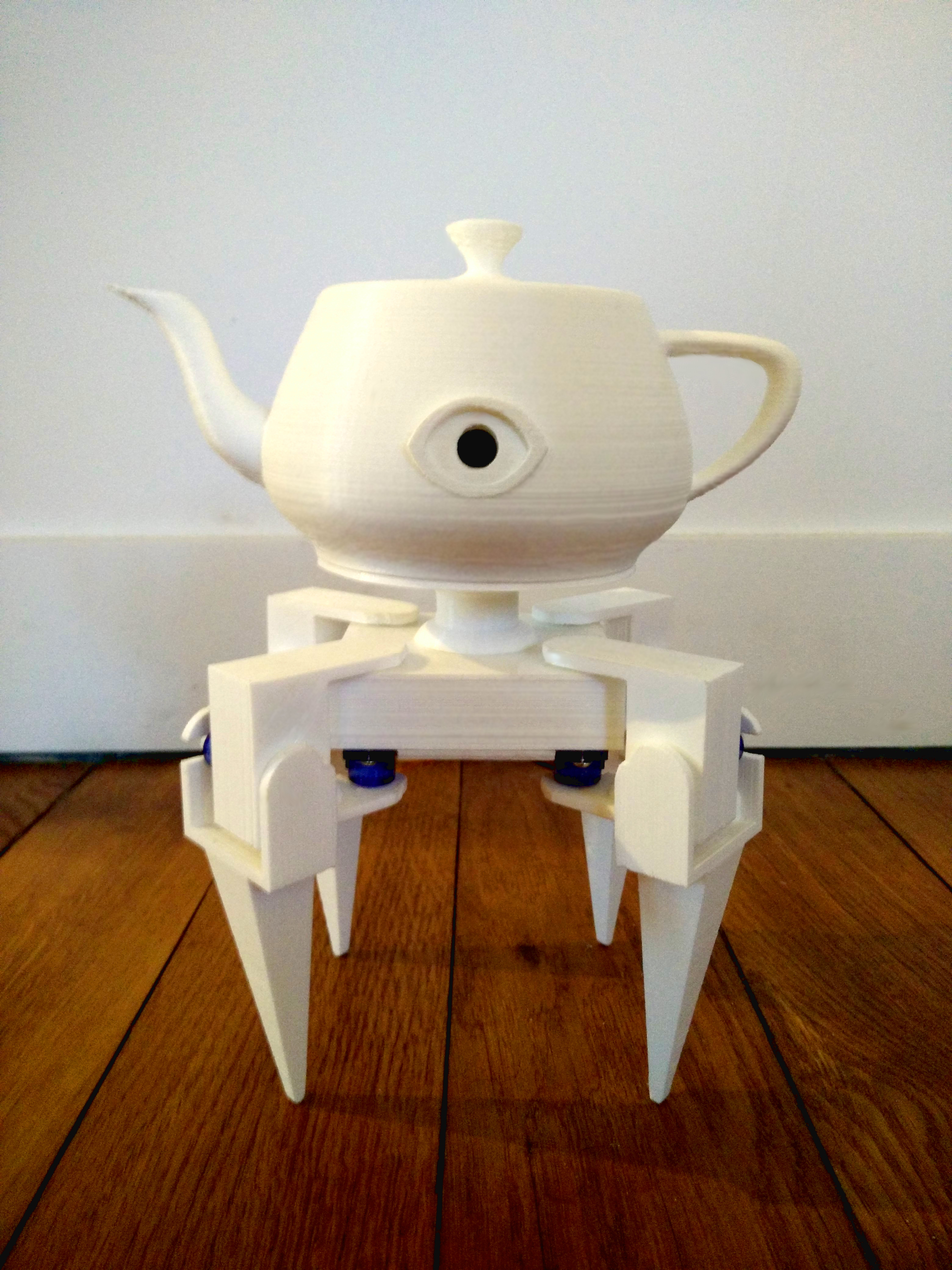
The finished Eyepot robot
Of course, the next step is to program the robot. We'll do it in my next article!
It's alive!

