This article is the continuation of my Minitel series: a Minitel as a Linux terminal, and a Minitel 2.0.
It's rather easy to remove legacy electronics and unmount the cathodic tube from the Minitel to replace them with a Raspberry Pi and a flat screen. However, the difficult part would be adapting the Minitel's proprietary keyboard.
Therefore, in this article, we will first make a generic USB keyboard controller for the Minitel 1B out of an Arduino board. We'll use an Arduino Pro Micro. It is roughly equivalent to the Pro Mini, except it has an on-board USB transceiver, which will allow us to configure it as a USB Keyboard. Then, we'll fit a 8-inch LCD panel to replace the old CRT. I chose an Innolux HE080IA-01D panel with driver board. Its dimensions and 1024x768 resolution make it a perfect candidate for our use case here.
The Minitel's keyboard is a simple matrix one. Key presses close circuits, and by continuously scanning the matrix, the controller can deduce which keys are pressed. Sadly, the matrix is non-standard, so we have to retro-engineer it...
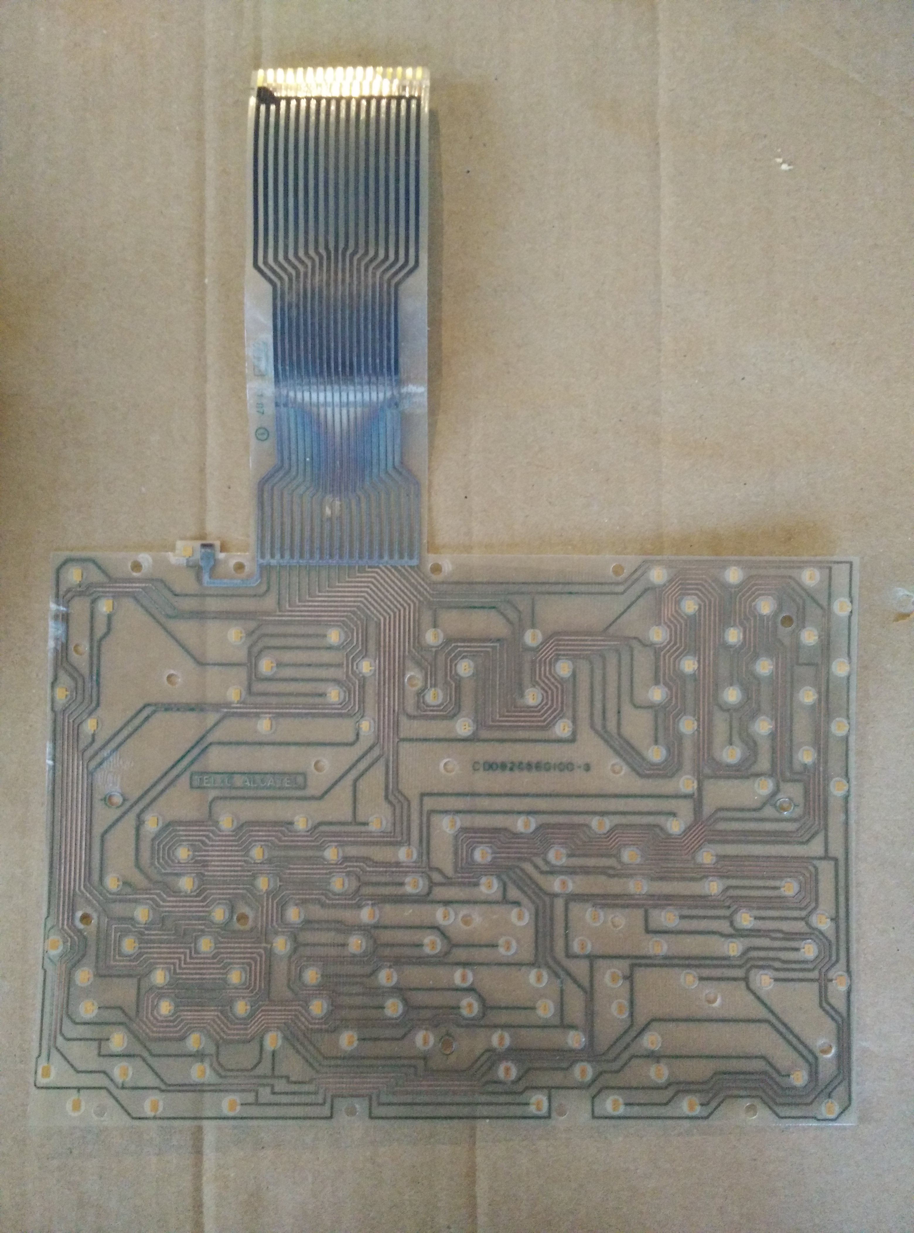
The keyboard contact board extracted from a Minitel
The easiest way is to sacrifice another Minitel, dismount the plastic-riveted metal enclosure of the keyboard, and retrieve the contact board from inside.
Guessing the matrix from the contact board is just like a labyrinth game, only a rather boring one. The tricky part is that I didn't even know beforehand which tracks of the ribbon cable corresponded to rows and columns. If you number tracks from the left starting at 0, it turns out the two groups are actually (1, 6, 7, 8, 9, 10, 11, 16) and (2, 3, 4, 5, 12, 13, 14, 15). I mean, why not?
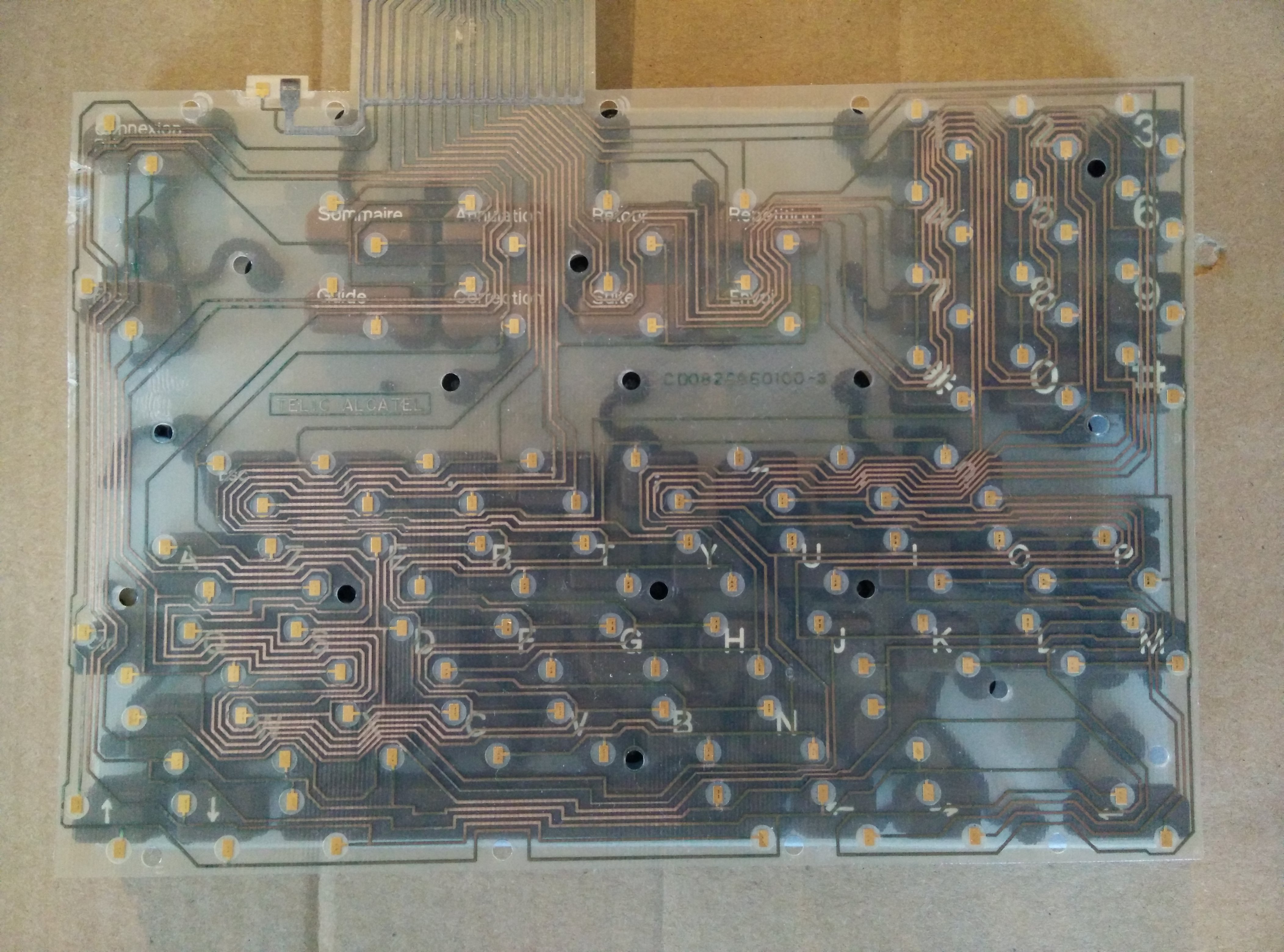
The contact board placed on top of the keyboard to highlight the mapping
In the end, we get the following mapping (from left to right, starting at 0):
*     1       6       7       8       9       10      11      16
   +------------------------------------------------------------------
2  |  Up      T       G       .       B       Guide   Fnct    Conn.
3  |  Corr.   E       D       Esc     C       Z       S       X
4  |  Ann.    R       F       ,       V       A       Q       W
5  |  Down    Y       H       '       N       Somm.   Ctrl    Space
12 |  Shift   ;       *       Suite   0       J       #       U
13 |  Left    -       7       Retour  8       K       9       I
14 |  Right   :       4       Envoi   5       L       6       O
15 |  Entrée  ?       1       Repet.  2       M       3       P
Track 0 is only shielding that we'll keep to the ground. In what follows, I will use (1, 6, 7, 8, 9, 10, 11, 16) as outputs and (2, 3, 4, 5, 12, 13, 14, 15) as inputs.
To connect the ribbon cable to the Arduino, I unsoldered the original connector from the previously sacrificed Minitel's main board and re-soldered in on an ad-hoc board.

The keyboard ribbon cable adapted to the Arduino
Key states will be scanned by pulling inputs high with their internal resistors, setting one output low while the others are high, then checking if one of the inputs is pulled down as a result. If an input is low, then the key at the corresponding intersection in the matrix is pressed, else, it's not. In a nutshell, we scan outputs while listening on inputs.
In this configuration, logical outputs are actually current sinks, so current must only flow to an output and not from it (this could happen when multiple keys are pressed), therefore we need one diode on each output line.

The custom-made keyboard controller connected to the Raspberry Pi
It would look silly to hook the USB connector to the Raspberry Pi from outside, so I chose to solder the wires directly under it. It still condemns a USB port, though.

The USB connector soldered directly under the Raspberry Pi
Then of course we need to program the Arduino to act as a keyboard controller. We use the Keyboard library to mimic a USB keyboard and send keystrokes. It is a bit more complex than explained previously, because we also need to take into account modifier keys (Shift, Ctrl, and Fnct), meaning there are actually four matrixes.
/*
 * Minitel 1B keyboard controller
 * Copyright (c) 2019 by Paul-Louis Ageneau
 *
 * This program is free software: you can redistribute it and/or modify
 * it under the terms of the GNU General Public License as published by
 * the Free Software Foundation, either version 3 of the License, or
 * (at your option) any later version.
 *
 * This program is distributed in the hope that it will be useful,
 * but WITHOUT ANY WARRANTY; without even the implied warranty of
 * MERCHANTABILITY or FITNESS FOR A PARTICULAR PURPOSE.  See the
 * GNU General Public License for more details.
 *
 * You should have received a copy of the GNU General Public License
 * along with this program.  If not, see <http://www.gnu.org/licenses/>.
 */

#include <Keyboard.h>

#define KEY_SHIFT KEY_RIGHT_SHIFT
#define KEY_CTRL  KEY_RIGHT_CTRL

#define MINITEL_SOMM    0xF0
#define MINITEL_ANNUL   0xF1
#define MINITEL_RETOUR  0xF2
#define MINITEL_REPET   0xF3
#define MINITEL_GUIDE   0xF4
#define MINITEL_CORREC  0xF5
#define MINITEL_SUITE   0xF6
#define MINITEL_ENVOI   0xF7
#define MINITEL_CONN    0xF8
#define MINITEL_FNCT    0xF9

// Keyboard ribbon cable is numbered 0|1|2 3 4 5|6 7 8 9 A B|C D E F|G (0 to ground)
// It's connected correspondingly to pins GND|2|3 4 5 6|7 8 9 10 16 14|15 18 19 20|21

// Pins mapping
const int pinCount = 8;
const int scanPins[pinCount] = { 2, 7, 8, 9, 10, 16, 14, 21 };   // outputs
const int listenPins[pinCount] = { 3, 4, 5, 6, 15, 18, 19, 20 }; // inputs

// Keyboard matrix
const int keyCount = pinCount * pinCount;
const int matrix[keyCount] = {
// 1                6    7    8               9    A              B             G
   KEY_UP_ARROW,    't', 'g', '.',            'b', MINITEL_GUIDE, MINITEL_FNCT, MINITEL_CONN, // 2
   MINITEL_CORREC,  'e', 'd', KEY_ESC,        'c', 'z',           's',          'x',          // 3
   MINITEL_ANNUL,   'r', 'f', ',',            'v', 'a',           'q',          'w',          // 4
   KEY_DOWN_ARROW,  'y', 'h', '\'',           'n', MINITEL_SOMM,  KEY_CTRL,     ' ',          // 5
   KEY_SHIFT,       ';', '*', MINITEL_SUITE,  '0', 'u',           'j',          '#',          // C
   KEY_LEFT_ARROW,  '-', '7', MINITEL_RETOUR, '8', 'i',           'k',          '9',          // D
   KEY_RIGHT_ARROW, ':', '4', MINITEL_ENVOI,  '5', 'o',           'l',          '6',          // E
   KEY_RETURN,      '?', '1', MINITEL_REPET,  '2', 'p',           'm',          '3',          // F
};

#define INDEX_SHIFT 4 * pinCount
#define INDEX_CTRL  3 * pinCount + 6
#define INDEX_FNCT  6

// Partial keyboard matrix for SHIFT key
const int matrixModShift[keyCount] = {
// 1      6     7     8     9     A     B     G
   0,     0,    0,    '>',  0,    '_',  0,    0,    // 2
   '~',   0,    0,    0,    0,    0,    0,    0,    // 3
   '\\',  0,    0,    '<',  0,    0,    0,    0,    // 4
   0,     0,    0,    '@',  0,    '^',  0,    0,    // 5
   0,     '+',  '[',  '`',  '|',  0,    0,    ']',  // C
   0,     '=',  '\'', '\'', '(',  0,    0,    ')',  // D
   0,     '*',  '$',  '}',  '%',  0,    0,    '&',  // E
   0,     '/',  '!',  '{',  '"',  0,    0,    '#',  // F
};

// Partial keyboard matrix for CTRL key
const int matrixModCtrl[keyCount] = {
// 1              6     7               8     9     A         B     G
   0,             0,    0,              0,    0,    0,        0,    0,    // 2
   0,             0,    0,              0,    0,    0,        0,    0,    // 3
   0,             0,    0,              0,    0,    0,        0,    0,    // 4
   0,             0,    KEY_BACKSPACE,  0,    0,    0,        0,    0,    // 5
   KEY_CAPS_LOCK, 0,    0,              0,    0,    0,        0,    0,    // C
   KEY_BACKSPACE, 0,    0,              0,    0,    KEY_TAB,  0,    0,    // D
   0,             0,    0,              0,    0,    0,        0,    0,    // E
   0,             0,    0,              0,    0,    0,        0,    0,    // F
};

// Partial keyboard matrix for FNCT key
const int matrixModFnct[keyCount] = {
// 1              6     7        8    9        A     B     G
   KEY_PAGE_UP,   0,    0,       0,   0,       0,    0,    0,         // 2
   0,             0,    0,       0,   0,       0,    0,    0,         // 3
   0,             0,    0,       0,   0,       0,    0,    0,         // 4
   KEY_PAGE_DOWN, 0,    0,       0,   0,       0,    0,    0,         // 5
   KEY_CAPS_LOCK, 0,    0,       0,   KEY_F10, 0,    0,    KEY_F11,   // C
   0,             0,    KEY_F7,  0,   KEY_F8,  0,    0,    KEY_F9,    // D
   0,             0,    KEY_F4,  0,   KEY_F5,  0,    0,    KEY_F6,    // E
   0,             0,    KEY_F1,  0,   KEY_F2,  0,    0,    KEY_F3,    // F
};

// Press state of keys
bool state[keyCount];

void event(int key, bool state) {
  Serial.print(state ? "D" : "U");
  Serial.println(key, HEX);

  // Convert Minitel-specific keys
  switch(key) {
    case MINITEL_SOMM:   key = KEY_HOME;      break;
    case MINITEL_ANNUL:  key = KEY_END;       break;
    case MINITEL_RETOUR: key = KEY_BACKSPACE; break;
    case MINITEL_REPET:  key = KEY_INSERT;    break;
    case MINITEL_GUIDE:  key = KEY_RIGHT_GUI; break;
    case MINITEL_CORREC: key = KEY_DELETE;    break;
    case MINITEL_SUITE:  key = KEY_TAB;       break;
    case MINITEL_ENVOI:  key = KEY_RETURN;    break;
    case MINITEL_CONN:   key = KEY_F12;       break;
  }

  if(state) Keyboard.press(key);
  else Keyboard.release(key);
}

void setup() {
  Serial.begin(9600);
  Keyboard.begin();

  // Initialize key states
  for(int k = 0; k < keyCount; ++k) {
    state[k] = false;
  }

  // Set outputs high
  for(int i = 0; i < pinCount; ++i) {
    pinMode(scanPins[i], OUTPUT);
    digitalWrite(scanPins[i], HIGH);
  }

  // Pull inputs up
  for(int j = 0; j < pinCount; ++j) {
    pinMode(listenPins[j], INPUT_PULLUP);
  }
}

void loop() {
  // Scan the keyboard matrix

  // Loop on outputs
  for(int i = 0; i < pinCount; ++i) {

    // Set output i to low
    digitalWrite(scanPins[i], LOW);

    // Loop on inputs
    for(int j = 0; j < pinCount; ++j) {

      // Key k is pressed if input j is low
      const int k = j*pinCount + i;
      const bool oldState = state[k];
      state[k] = (digitalRead(listenPins[j]) == LOW);

      // Handle key state change
      if(state[k] != oldState) {
        if(state[INDEX_FNCT] && matrixModFnct[k]) {
          event(matrixModFnct[k], state[k]);
        }
        else if(state[INDEX_CTRL] && matrixModCtrl[k]) {
          event(KEY_CTRL, false);
          event(matrixModCtrl[k], state[k]);
          event(KEY_CTRL, true);
        }
        else if(state[INDEX_SHIFT] && matrixModShift[k]) {
          const int key = matrixModShift[k];
          event(KEY_SHIFT, false);
          event(key, state[k]);
          event(KEY_SHIFT, true);
        }
        else {
          event(matrix[k], state[k]);
        }
      }
    }

    // Reset output i to high
    digitalWrite(scanPins[i], HIGH);
  }
}
You may have noticed that the Raspberry Pi is fitted in the same custom rear panel as in my previous article.
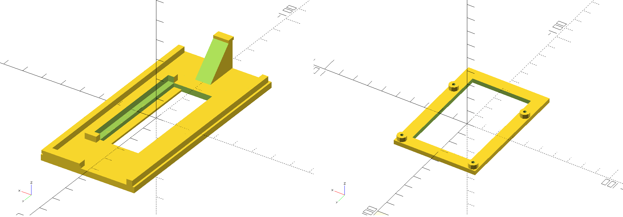
Replacement for the rear panel holding the Raspberry Pi
To attach the LCD screen, we'll take advantage of the former anchoring points of the CRT screen, which have been previously sawn. I printed specifically-designed holding pieces and screwed them into the holes in the frame so they keep the screen in place. Since the former screen was not flat, it leaves holes on the sides that I filled with black masking tape.
STL models with OpenSCAD sources are available here (under GPLv3).

The LCD screen attached on the Minitel frame

Close-up of a screen holder screwed to the frame
I added a limit switch to make the on/off push button work again. The switch will be connected to the Pi's GPIO, and will allow to turn the screen and the LED on and off.

New switch for the on/off push button
I replaced the power plug with a 12V socket, feeding the LCD driver board directly and the Raspberry Pi through a 5V UBEC. Of course the LCD board is also connected to the Pi's HDMI output with a short cable. Note the red LED, powered via the GPIO, which will replace the Minitel power-on LED next to the on/off button.
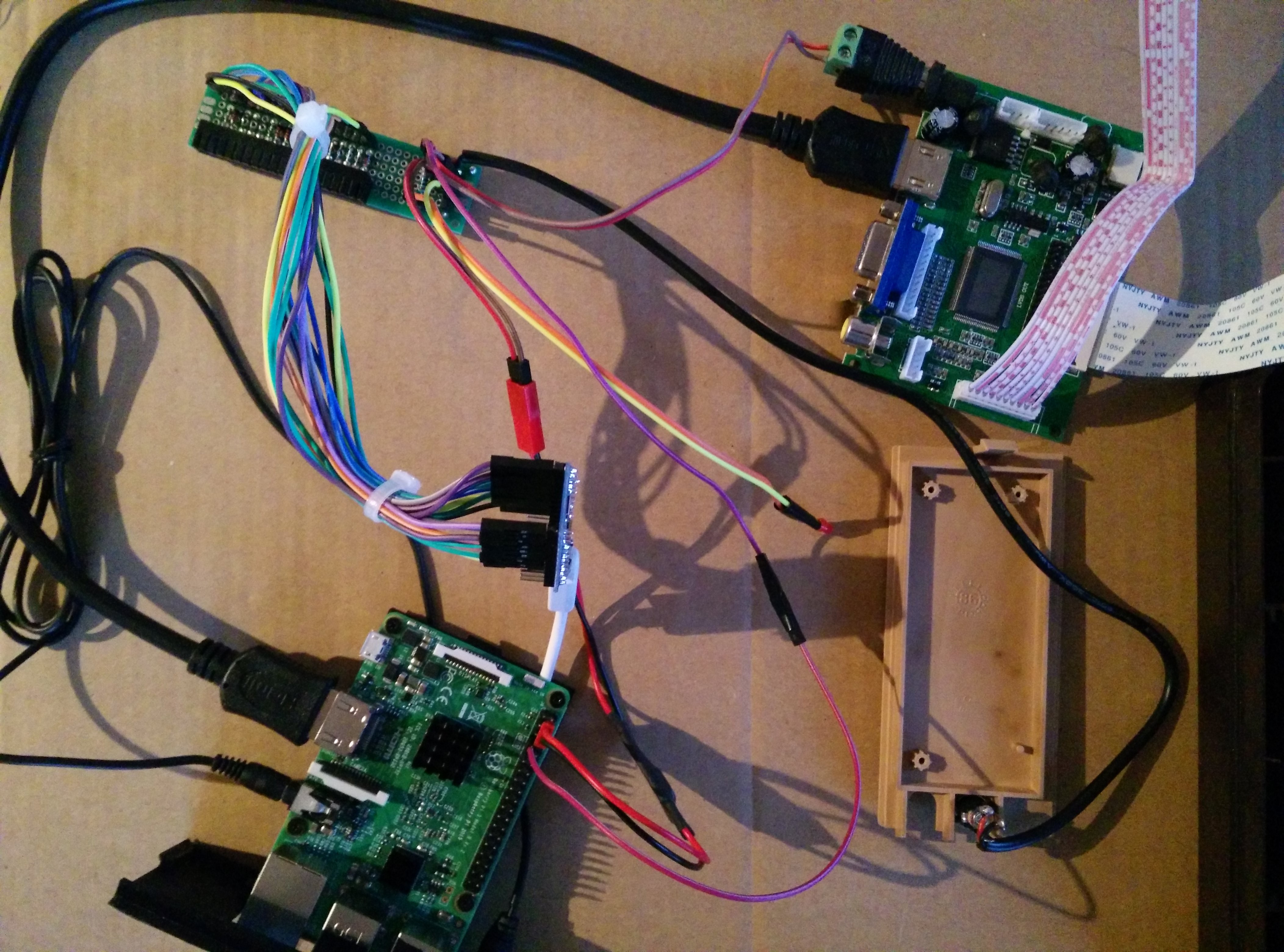
Everything connected together
Eventually, the last step is to put everything in the Minitel box and close it. Then we can connect the power via a 12V adapter, let the Raspberry Pi boot on Raspbian, and... it works!

It works!
The final step is to install a custom Python script to handle the power button and LED.
#!/usr/bin/env python3
# -*- coding: utf-8 -*-

import time
import subprocess
import RPi.GPIO as GPIO

PIN_LED = 7
PIN_BUTTON = 11
BUTTON_DELAY = 0.05

# Setup GPIO
GPIO.setwarnings(False)
GPIO.setmode(GPIO.BOARD)
GPIO.setup(PIN_LED, GPIO.OUT)
GPIO.setup(PIN_BUTTON, GPIO.IN, pull_up_down=GPIO.PUD_UP)

def wait_button():
    time.sleep(BUTTON_DELAY)
    GPIO.wait_for_edge(PIN_BUTTON, GPIO.FALLING)
    time.sleep(BUTTON_DELAY)
    while GPIO.input(PIN_BUTTON) == GPIO.LOW:
        GPIO.wait_for_edge(PIN_BUTTON, GPIO.RISING)

def set_led(on):
    GPIO.output(PIN_LED, GPIO.HIGH if on else GPIO.LOW)

def set_display_power(on):
    subprocess.call(["vcgencmd", "display_power", str(1 if on else 0)])


if __name__ == "__main__":
    state = False
    while True:
        state = not state
        set_display_power(state)
        set_led(state)
        wait_button()
We only need to run it at startup, for instance via a crontab @reboot line, to make a first press on the power button turn off both the display and the LED, and a second one turn them both on again. It mimics the original behavior well enough!

