The original Furby from Tiger Electronics was a huge phenomenon at the end of the 1990s. In this article, we are going to replace a Furby's electronics to transform it into a USB-controlled puppet.

The blue-eyed brown-bellied cute horror
The little beaked Mogwais looked quite alive and faked learning processes pretty well. As electronic talking toys were still a novelty back then, its capacities were grossly over-estimated, especially among children. For instance, the microphone is limited to sensing the noise level to talk back when you talk to it, it is actually unable to differentiate noises, let alone interpret speech.
In reality, the technology was already old. As the patent indicates, Furbys were built around a 8-bit SunPlus SPC81A microcontroller, basically a crippled 6502 processor with 128 bytes of RAM (yes, bytes). The original MOS Technology 6502 processor was introduced in 1975 and became pretty popular because it was extremely cheap. For instance, the Atari 2600 and Apple II were both built around modified 6502 processors. It was a strong influence in the design of RISC architectures, in particular ARM processors. The voice synthesis is handled by a Texas Instruments TSP50C04 running an LPC (Linear Predictive Coding) codec which imitates the human vocal tract to reproduce audio, a technology that became common in the 1980s for speaking toys. This sounds a bit ironic as it seems that the SunPlus SPC81A, here used as main processor, was itself designed as a speech and melody synthesizer.
As widely-available customer devices with audio capabilities, Furbys have been quite popular in the circuit-bending community. You should definitely have a look at the nightmarish Furby Organ built by Sam Battle a.k.a. Look Mum No Computer.
Here, we are not going to focus on the audio part, but on the mechanical part.
Why work on a Furby? Well, in a bubbly world where lots of people just want to throw their beans at any form of Beanie Babies available to magically increase their stash (Get it? Because of magic beans!), it's good to keep it real and tinker on other things. But I digress, the point is that we are operating a Furby here, not a Beanie Baby.
Disassembly
We'll start by skinning the Furby. The fur is placed like on a sock puppet and attached around the base with a clamp. To access it, you need to unstitch a few threads at the back of the base. Then you can cut the clamp and start cautiously skinning the Furby from bottom to top. The face plate is glued to the body and is a bit challenging to remove. Finally, there are also stitches to remove on the ears.
Under the fur, the Furby has a carapace made of two pieces on each side. After unscrewing them, the Furby reveals its internal mechanism.
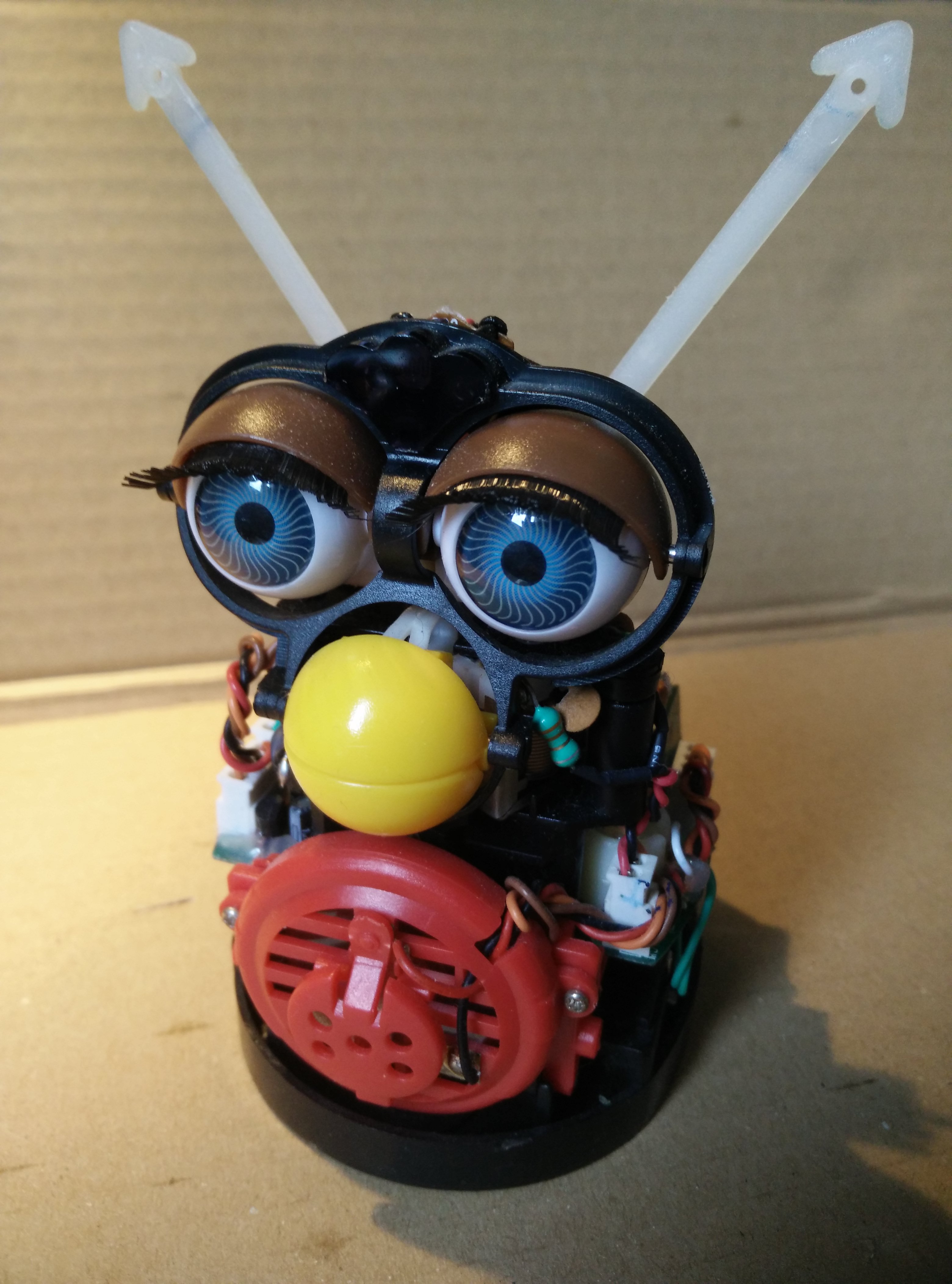
The original Furby with its fur and carapace removed
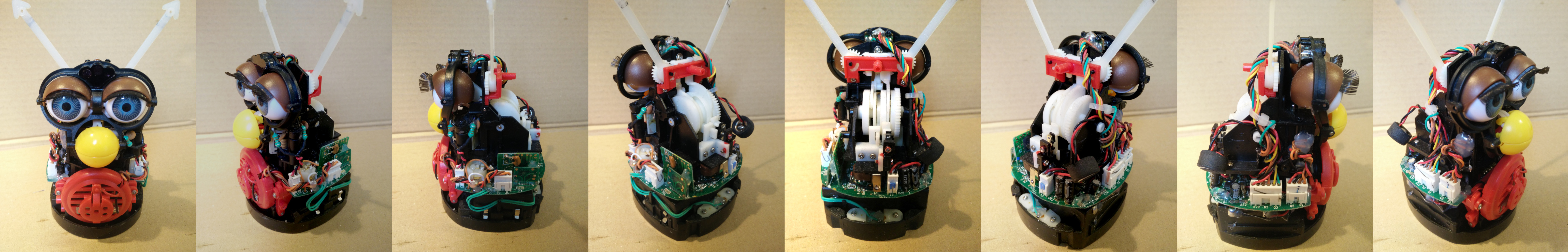
360-degree view of the Furby with its fur and carapace removed
The entire set of movements of the Furby, opening and closing its eyes and mouth, moving its ears, and making it bend forward, is controlled by a single DC motor. The internal mechanism is indeed quite ingenious and works a bit like an old-fashioned automaton: a camshaft encodes the different gestures one after the other, and various sequences of gestures can be achived by simply rotating the camshaft back and forth.

Removing the front speaker and touch sensor

The disassembled Furby
The exact position of the shaft is tracked with some sort of custom-made rotation sensor, which works similarly to sensors you could find in ball mouses. An infrared LED, positioned on the main board, emits light in a vertical tunnel going through a perforated gear. On the top side of the tunnel, a tiny photodetector is illuminated or not depending on the gear position. While the motor runs, the traveled angle can be measured by counting the illuminations. The initial position is known thanks to a mechanical interruptor closed when the shaft is home, which is not extremely precise but sufficient for the purpose.
Replacing electronics
We'll remove the original electronic board and replace it with an Arduino Pro Micro fitted in the battery compartment. We'll also add a H-bridge to drive the motor and a amplifier to get some sound to the speaker.
We'll use:
- Arduino Pro Micro 5V 16MHz
- H-bridge Motor Driver (TB6612FNG)
- Amplifier module (LM386)
- Thin 40mm 8Ω speaker
- Micro USB and jack cables
- Infrared LED, resistors, capacitor (> 100µF)
- Dupont wires and some other stuff
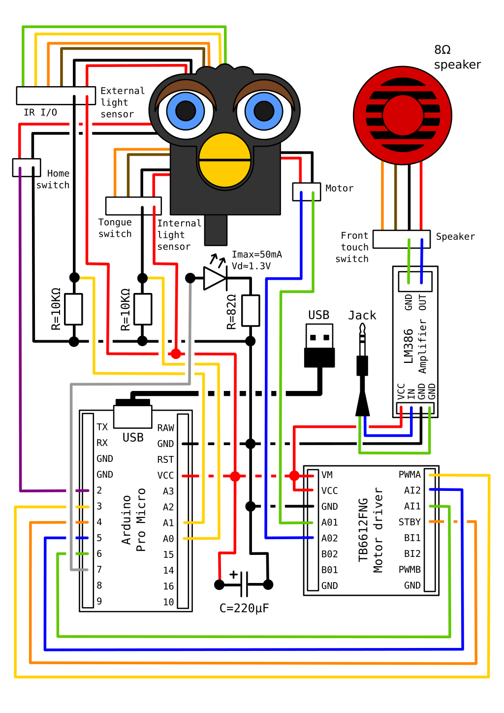
General schematic of connections
Note everything is powered through the USB 5V power via the Arduino Vcc pin. No batteries needed!
The home switch pulls the corresponding Arduino pin down to ground, we'll therefore activate the internal pull-up resistor for the pin. The tongue, touch, and even reset switches could also be connected the same way. The two light sensors, the internal one for the rotation sensor and the external one, are both connected as voltage dividers with 10KΩ resistors: the higher the voltage around the resistor, the stronger the light.
I replaced the rotation sensor 5mm LED with a similar infrared one (540nm). It requires a current under 50mA and introduces a voltage drop of around 1.3V, therefore we should couple it with a resistor above 74Ω. In pratice, I coupled it with a 82Ω resistor and measured that in real conditions (actual Vcc is less than 5V, etc) the resulting current is between 30mA and 40mA, which is actually close to the maximum the Arduino can output through a pin.
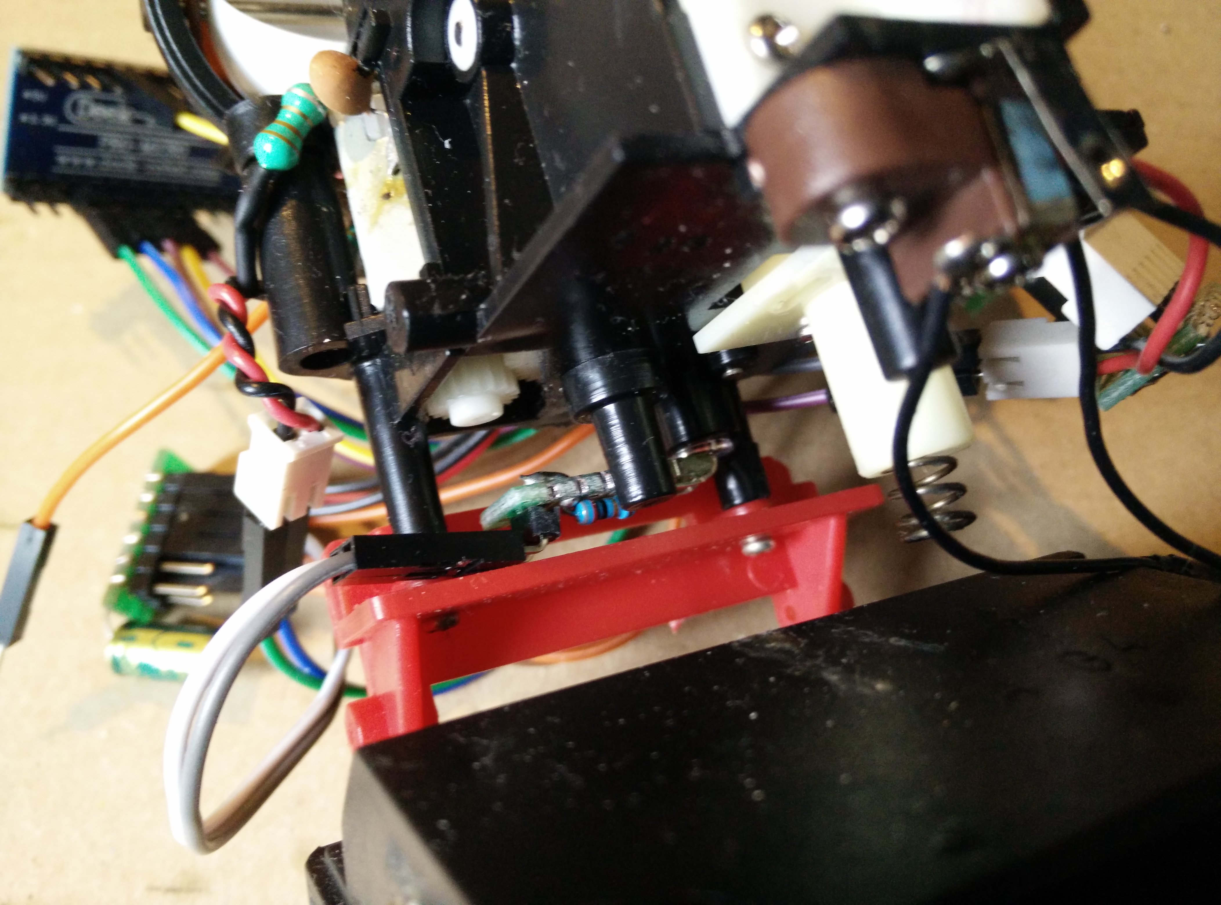
The rotation sensor LED replaced with a new one
Powering a motor from USB is a bit trickier than from a LiPo battery. Indeed, whereas the battery can temporarily provide a high current when the motor starts or stalls, the available current on USB 5V power is limited to only 900mA for USB 3.0 and 500mA for USB 2.0. This is an issue as the Arduino is powered from the same source, so operating the motor tends to drop the voltage and reboot the Arduino. Therefore, we need to put a decoupling capacitor on the 5V rail to prevent drops. I chose a big 220μF one and everything works fine. Decoupling capacitors are like magic.
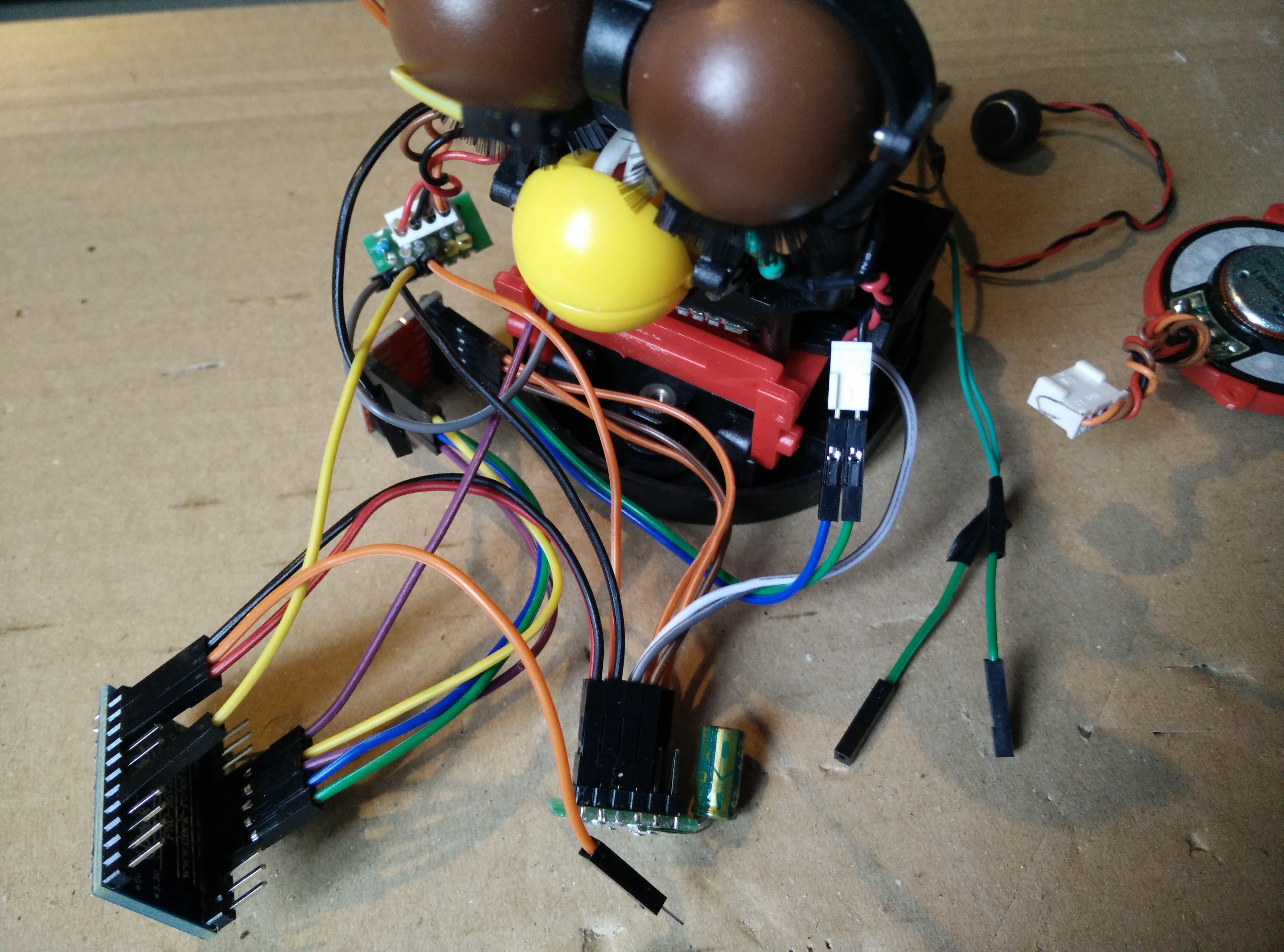
Testing the connections
Controlling the Furby's movement is fine but it's better to have it talking too. The default speaker is a cheap 40mm 32Ω headphone speaker, whose impedence is too high for the use case. It is basically impossible to drive it at loud enough volumes without distorting like crazy with a good old LM386 amplifier module, therefore I replaced it with a better-suited 40mm 8Ω speaker.
Motor connection and power distribution with decoupling capacitor on the left side

Both light sensors connected on the right side
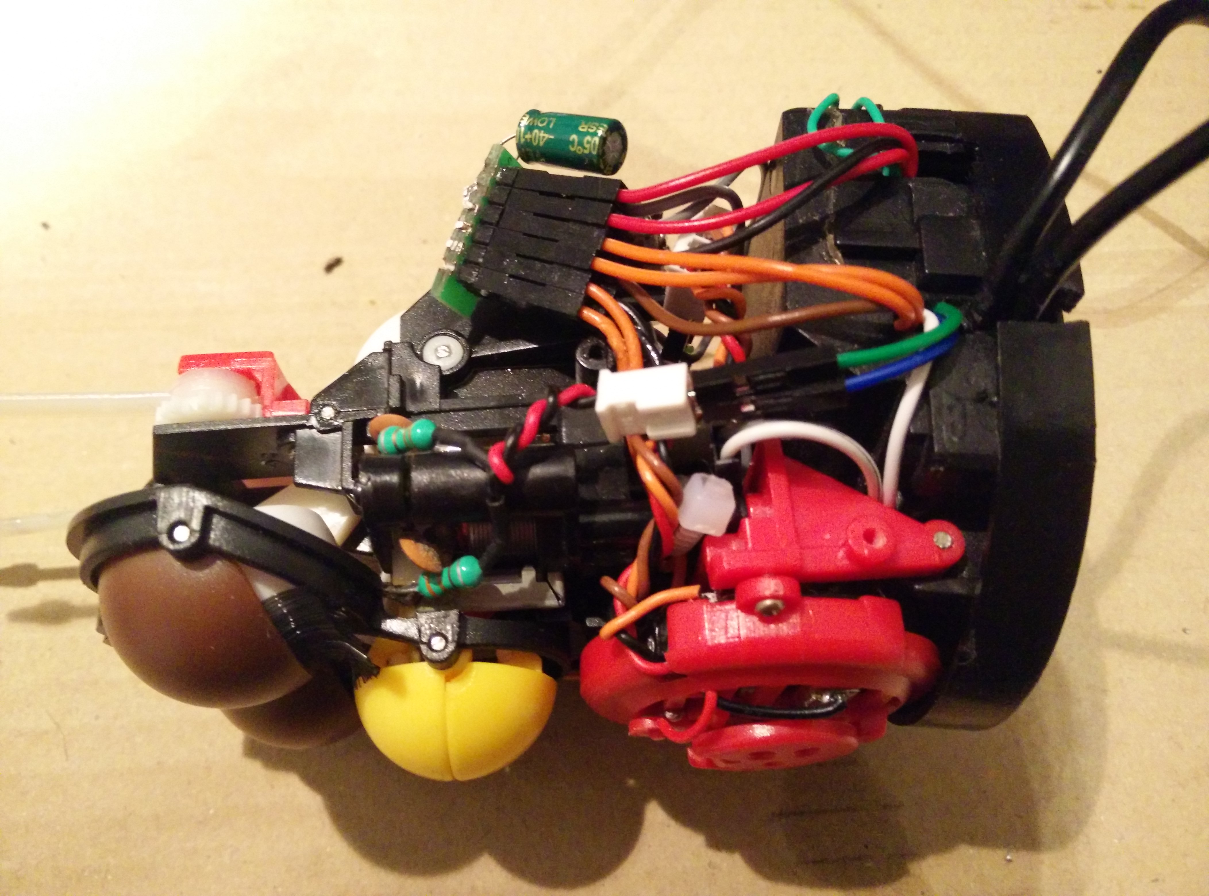
Everything fits in the battery compartment once the battery contactors have been removed and the separators have been cut down. It's a tight fit, but it wasn't even necessary to solder the cables to make some space by removing the Dupont connectors.

Everything fits in the repurposed battery compartment
I cut a hole on the side for both cables (USB and Jack) to get out. The carapace needs to be cut at the same spot, with some leeway since the base moves independently from the carapace when the furby bends forward. We can finally put the fur back on.

The Furby put together again without its fur

The Furby with its fur back on
It's now time to program the modified Furby!
Programming
Motor control is pretty straightforward. The motor is powered via a H-bridge controlled with 4 pins: standby, forward, reverse, and PWM. Standby must be pulled high for the H-bridge to be powered, forward and reverse control polarity, while PWM controls the duty cycle of motor power.
void begin() {
    pinMode(MOTOR_PWM_PIN, OUTPUT);
    pinMode(MOTOR_STANDBY_PIN, OUTPUT);
    pinMode(MOTOR_FORWARD_PIN, OUTPUT);
    pinMode(MOTOR_REVERSE_PIN, OUTPUT);

    digitalWrite(MOTOR_STANDBY_PIN, HIGH);
}

void motor(int value) { // value 0 means brake
    digitalWrite(MOTOR_FORWARD_PIN, value >= 0 ? HIGH : LOW);
    digitalWrite(MOTOR_REVERSE_PIN, value <= 0 ? HIGH : LOW);
    analogWrite(MOTOR_PWM_PIN, constrain(abs(value), 0, 255));
}
Homing the camshaft is achieved by simply rotating it until the home sensor pin is triggered. The home sensor switch connects the pin pulled up to ground, therefore, it pulls the pin low when triggered.
void begin() {
    [...]
    pinMode(HOME_SENSOR_PIN, INPUT_PULLUP);
}

void home() {
    motor(MOTOR_POWER);
    while(digitalRead(HOME_SENSOR_PIN) == HIGH) {}
    motor(0);
}
To animate the Furby, we count the steps thanks to the internal light sensor: we light the LED, measure the illumination and count one step each time the illumination changes.
I measured that a full revolution of the camshaft corresponds to 208 illuminations of the rotation sensor. I mean, why not. Since we will count a step for each change of illumination state, the full revolution will correspond to 416 steps.
Of course, we need some hysteresis to prevent counting each illumination multiple times (The issue could easily happen if the motor stops on the threshold). The parity of the counter allows keeping track of the illumination state: even when dark, odd when light.
const int MOTOR_STEPS    = 416; // full revolution, as measured on my Furby
const int MOTOR_FORWARD  = 1;
const int MOTOR_BACKWARD = -1;
const int MOTOR_IDLE     = 0;

int currentStep = 0;             // Rotation step counter
int motorDirection = MOTOR_IDLE; // We will set this to the current direction

void begin() {
    [...]
    pinMode(LED_PIN, OUTPUT);
}

void update() {
    // Count steps using the internal light sensor
    if(motorDirection != MOTOR_IDLE) {
        digitalWrite(LED_PIN, HIGH); // turn the LED on
        int value = analogRead(INT_LIGHT_SENSOR_PIN); // measure
        digitalWrite(LED_PIN, LOW); // turn the LED off

        int parity = currentStep % 2;
        if((parity == 0 && value > INT_LIGHT_SENSOR_HIGH_THRESHOLD) ||
           (parity == 1 && value <= INT_LIGHT_SENSOR_LOW_THRESHOLD)) {
            currentStep = (MOTOR_STEPS + currentStep + motorDirection) % MOTOR_STEPS;
        }
    }
}
We can now track the current position. In order to move to a target postion, we rotate the motor forwards or backwards according to the difference between positions (computed like as a difference between angles), until the difference becomes small enough. As the position gets closer to the target position, the motor speed is reduced to help preventing an overshoot.
The trick is that the motor direction can't be changed abruptly, as we would lose track of the current position. The motor does indeed not reverse immediately, so we wouldn't know how to count the next steps. Therefore, we have to stop the motor, wait for it to actually stop, then reverse it.
int targetStep = 0; // Target rotation step
unsigned long motorLastTime = 0;

int distance(int to) {
    return ((currentStep - to) + MOTOR_STEPS/2 + MOTOR_STEPS) % MOTOR_STEPS - MOTOR_STEPS/2;
}

void update() {
    // Count steps using the internal light sensor
    [...]

    // Compare current position with target
    int dist = distance(targetStep);
    int dir = dist < 0 ? MOTOR_FORWARD : MOTOR_BACKWARD;
    if(abs(dist) > MOTOR_STEPS_TOLERANCE && (motorDirection == MOTOR_IDLE || motorDirection == dir)) {
        // Move to target
        motorDirection = dir;
        motorLastTime = millis();
        int power = map(constrain(abs(dist),
                        0, MOTOR_STEPS_POWER_MAX),
                        0, MOTOR_STEPS_POWER_MAX, MOTOR_POWER_MIN, MOTOR_POWER_MAX);
        motor(motorDirection * power);
    }
    else {
        // Target is reached or motor is in the wrong direction
        motor(0);

        // The motor does not stop instantaneously
        if(millis() - motorLastTime >= MOTOR_IDLE_DELAY) {
          motorDirection = MOTOR_IDLE;
        }
    }
}
The Furby features an external light sensor on its forehead. I connected it just like the internal light sensor, so we can retrieve a value for the ambient light level as seen by the Furby.
int light() {
    int value = analogRead(EXT_LIGHT_SENSOR_PIN);
    return map(value, 0, 1023, 0, 255);
}
The last step is to actually implement the setup and loop function to read commands from serial, which will allow to control the Furby.
String inputString = "";
bool targetReached = false;

void setup() {
    Serial.begin(9600);
    furby.begin();
    furby.home();
}

void loop() {
     // Read commands on serial
    while(Serial.available()) {
        char chr = (char)Serial.read();
        if(chr != '\n') {
            if(chr != '\r')
                inputString+= chr;
        }
        else if(inputString.length() > 0) {
            // Parse command
            char cmd = toupper(inputString[0]);
            String param;
            int pos = 1;
            while(pos < inputString.length() && inputString[pos] == ' ') ++pos;
            param = inputString.substring(pos);

            // Execute command
            switch(cmd) {
                case 'H':
                    furby.home();
                    Serial.println("H");
                    break;
                case 'M':
                    furby.target(param.toInt());
                    targetReached = false;
                    break;
                case 'L':
                    Serial.print("L ");
                    Serial.println(furby.light());
                    break;
                default:
                    Serial.println("E");
                    break;
            }

            inputString = "";
        }
    }

    furby.update();

    if(!targetReached && furby.reached()) {
        targetReached = true;
        Serial.print("M ");
        Serial.println(furby.target());
    }
}
On the computer, we can now easily control the Furby via the USB serial.
Here is an example class in Python:
# control.py

import enum
import serial
from concurrent.futures import ThreadPoolExecutor

TIMEOUT = 5

class Move(enum.IntEnum):
    EARS_UP = 0
    EARS_UP_MOUTH_OPEN = 50
    EYES_CLOSED = 130
    EARS_DOWN_EYES_CLOSED = 180
    EARS_DOWN = 300
    EARS_DOWN_MOUTH_OPEN = 350


class Control:
    def __init__(self, device='/dev/ttyACM0', baudrate=9600):
        self.serial = serial.Serial(device, baudrate, timeout=TIMEOUT)
        self.executor = ThreadPoolExecutor(max_workers=1)

    def write(self, cmd):
        self.serial.write((cmd + '\n').encode())

    def read(self):
        return self.serial.readline().decode()

    def run(self, cmd, arg=None):
        if arg is not None:
            self.write('{} {:d}'.format(cmd, int(arg)))
        else:
            self.write(cmd)

        ans = self.read()
        if ans is None:
            raise TimeoutError("Furby: command timeout")
        elif ans[0] != cmd[0]:
            raise RuntimeError("Furby: command error")
        else:
            ansarg = ans[1:].strip()
            return int(ansarg) if len(ansarg) > 0 else None

    def submit(self, cmd, arg=None):
        return self.executor.submit(self.run, cmd, arg)

    def light(self):
        light = self.submit('L').result()
        return light if light is not None else 0

    def home(self):
        self.submit('H').result()

    def move(self, target):
        self.submit('M', int(target)).result()
And here is how to use it:
#!/usr/bin/env python

from control import Control, Move

control = Control('/dev/ttyACM0')
control.home()
control.move(Move.EARS_UP)
control.move(Move.EARS_UP_MOUTH_OPEN)
control.move(Move.EARS_UP)
control.move(Move.EARS_UP_MOUTH_OPEN)
control.move(Move.EYES_CLOSED)
All we need now is espeak-ng, an mbrola voice, a touch of pitch distorsion, and some Python code to sync the lip movement, and the Furby speaks!
The whole source code for the project is available on my GitHub (under GPLv3).
The Furby speaks!

