Telepresence robots are pretty cool, so let's build my own Telebot!
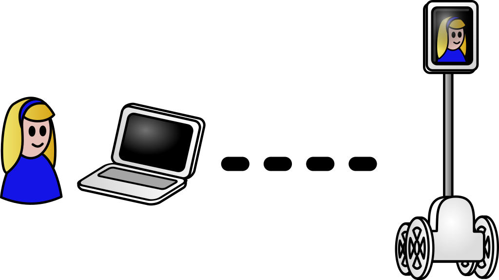
The telepresence robot allows visioconferencing while moving around
The robot will be built as a base with 4 wheels, on top of which a vertical pole allows to stick a smartphone. The smartphone, connected to the base via Bluetooth, will permit visioconference via WebRTC and remote control at the same time, allowing to move around. Even if the center of gravity is quite high, a gyroscope will prevent the robot from falling over. The base will be powered by lithium-polymer batteries and rechargeable via a USB connector.
This article covers building the robot, while the next article focuses on programming it.
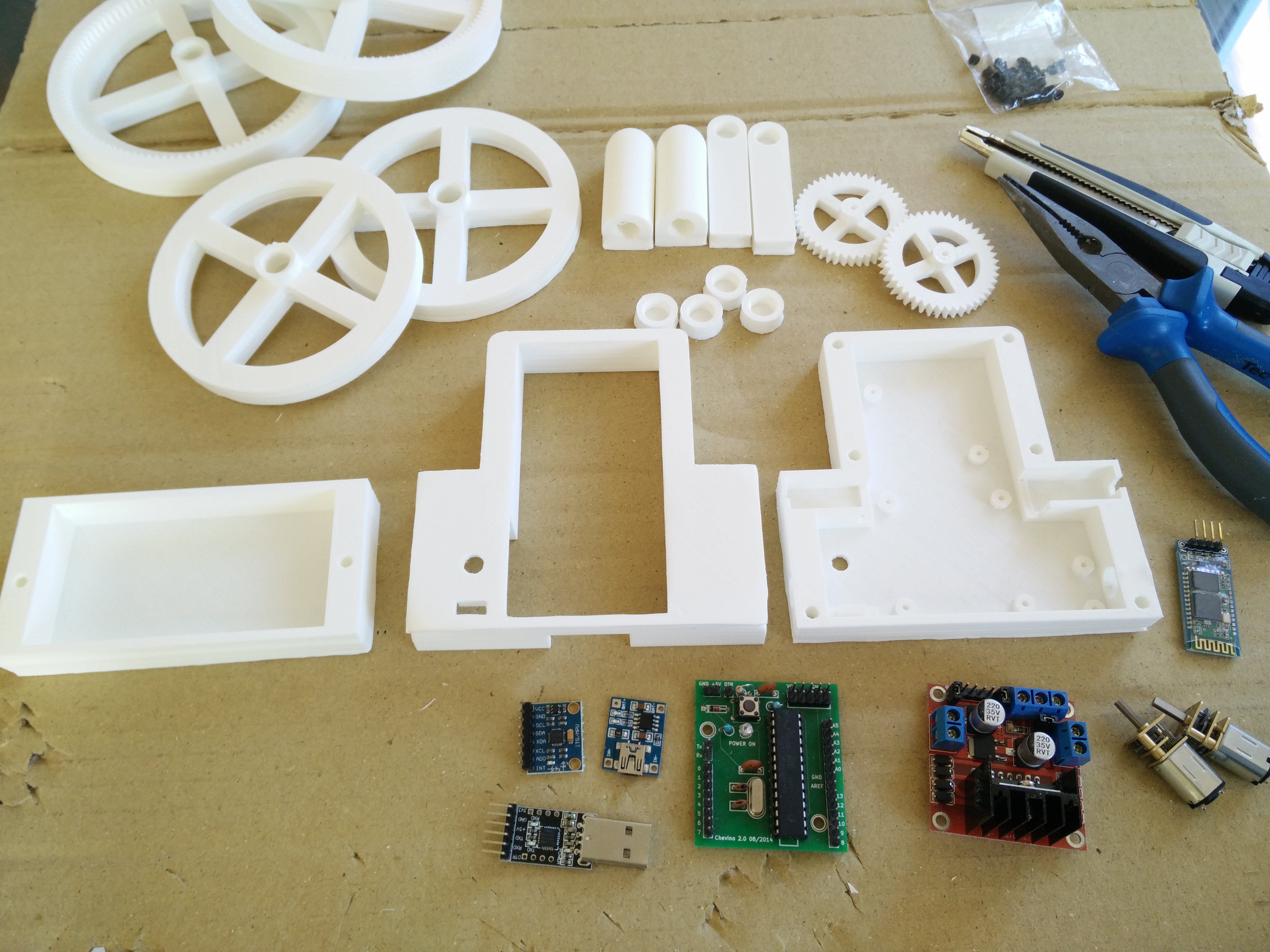
We will use the following components:
- Chevino: an Arduino Pro Mini clone (any other clone will do the job)
- L298N: Dual H-bridge with 5V regulated output
- MPU-6050: Accelerometer and gyro with I2C interface
- HC-06: Slave serial Bluetooth module
- TP4056: 5V 1A linear single-cell lipo battery charger with mini-USB port
- 2 DC motors: 6V 150RPM geared DC motors with 3mm shaft
- 2 lipo batteries: Single-cell 1200mAh 25C lithium-polymer batteries
- DPDT switch: Double-Pole Double-Throw switch (MTS-203 type)
- A USB to UART bridge to program the robot
- Aluminium tubes, diameter 1cm, for the pole and the wheels axes
- Wires, screws, epoxy glue and some other stuff
The Chevino is a simplified Arduino Uno clone built by my friend Paul Chevalier (see the article on his blog, in French). Close to the Arduino Pro Mini without the voltage regulator, it features an ATmega328P at 20 MHz. Thanks again, Paul ;)
First, let's design the pieces with OpenSCAD in order to 3D print them. The Telebot is made of 11 different plastic pieces, and a total of 19 pieces have to be printed. The base is slightly rounded and somewhat aesthetically pleasing, because I like a decent appearance even for a DIY project! You can download the SCAD source files and the corresponding STL files here (licensed under GPLv3). You may also find them in my repository on GitHub.
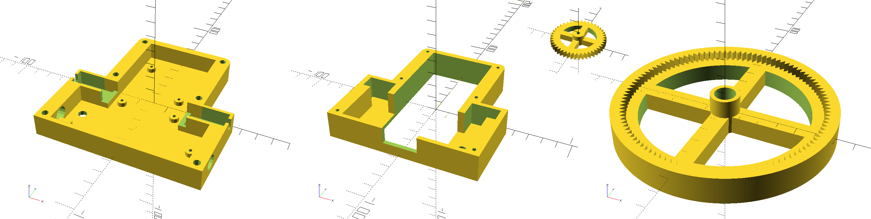
3D models of the back frame, the front frame, the wheel gear and the wheel
Once the pieces are designed, let's print them. I use PLA, which I find better than ABS. It is biodegradable, does not smell while printing and emits way less nanoparticles in the air.
When everything is printed, we have to assemble the robot! The boards are fixed with M2x4mm screws. First the Chevino is screwed at the top of the back panel, and the L298N at the bottom.
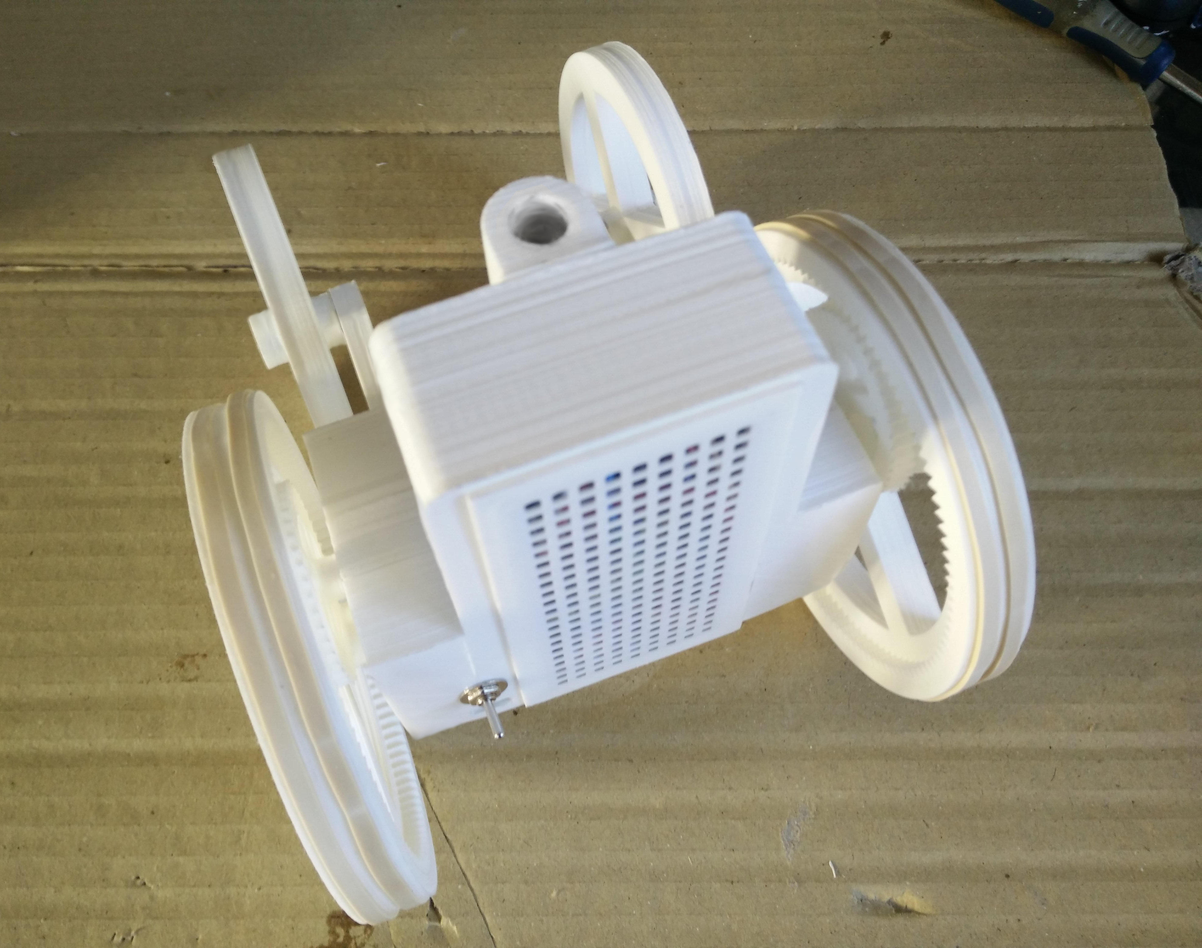
Every part is printed, the robot is now ready to be built
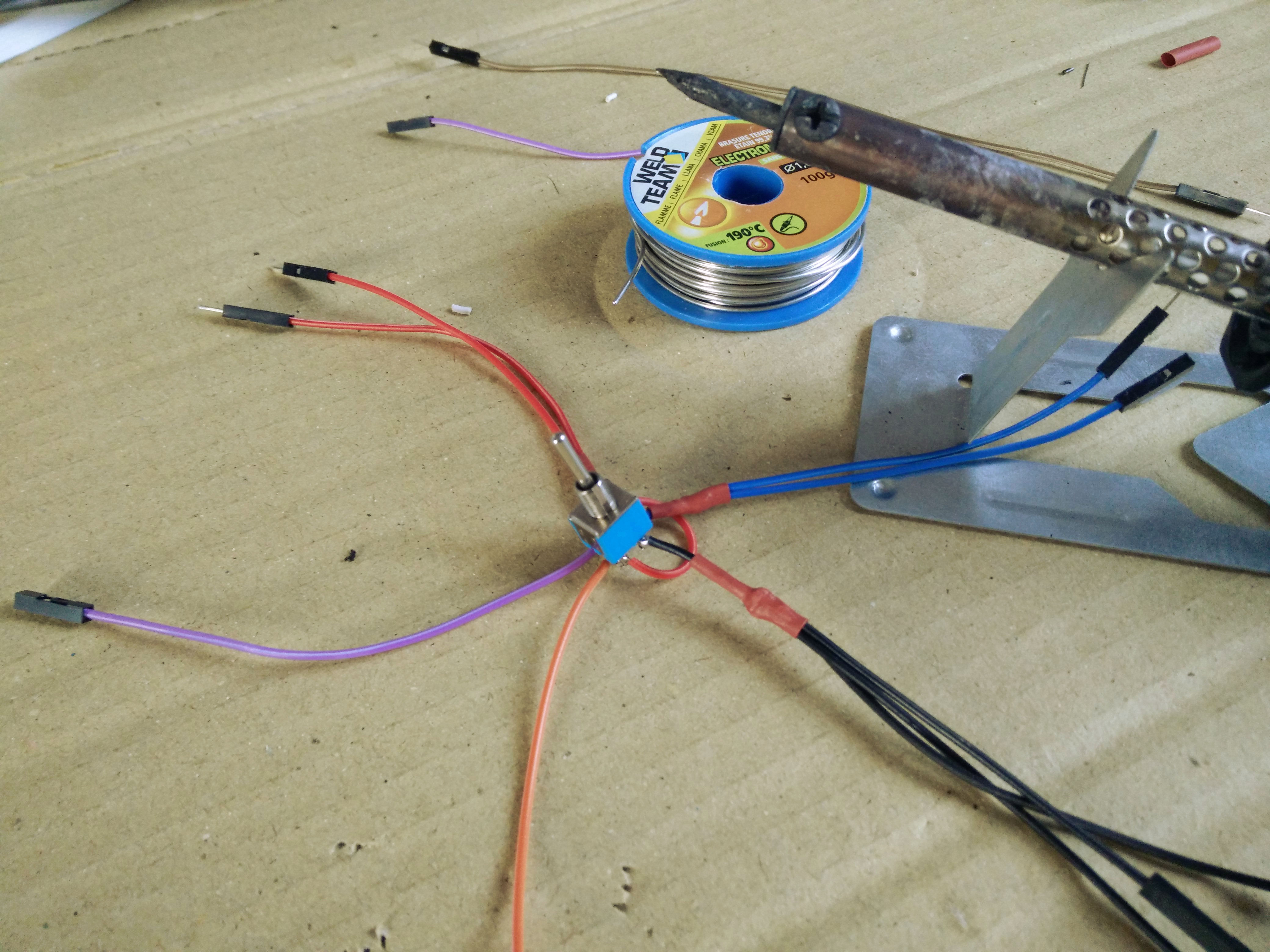
Since the motors are brushed, we need to add two parallel capacitors to absorb noise created by the arcing as the brushes commutate, because it would interfere with the electronics, particularly I2C transmission. Capacitors of 100nF should be OK. Besides, we will use PWM to drive the motors, so they will also help reduce voltage spikes caused by motor inductance.
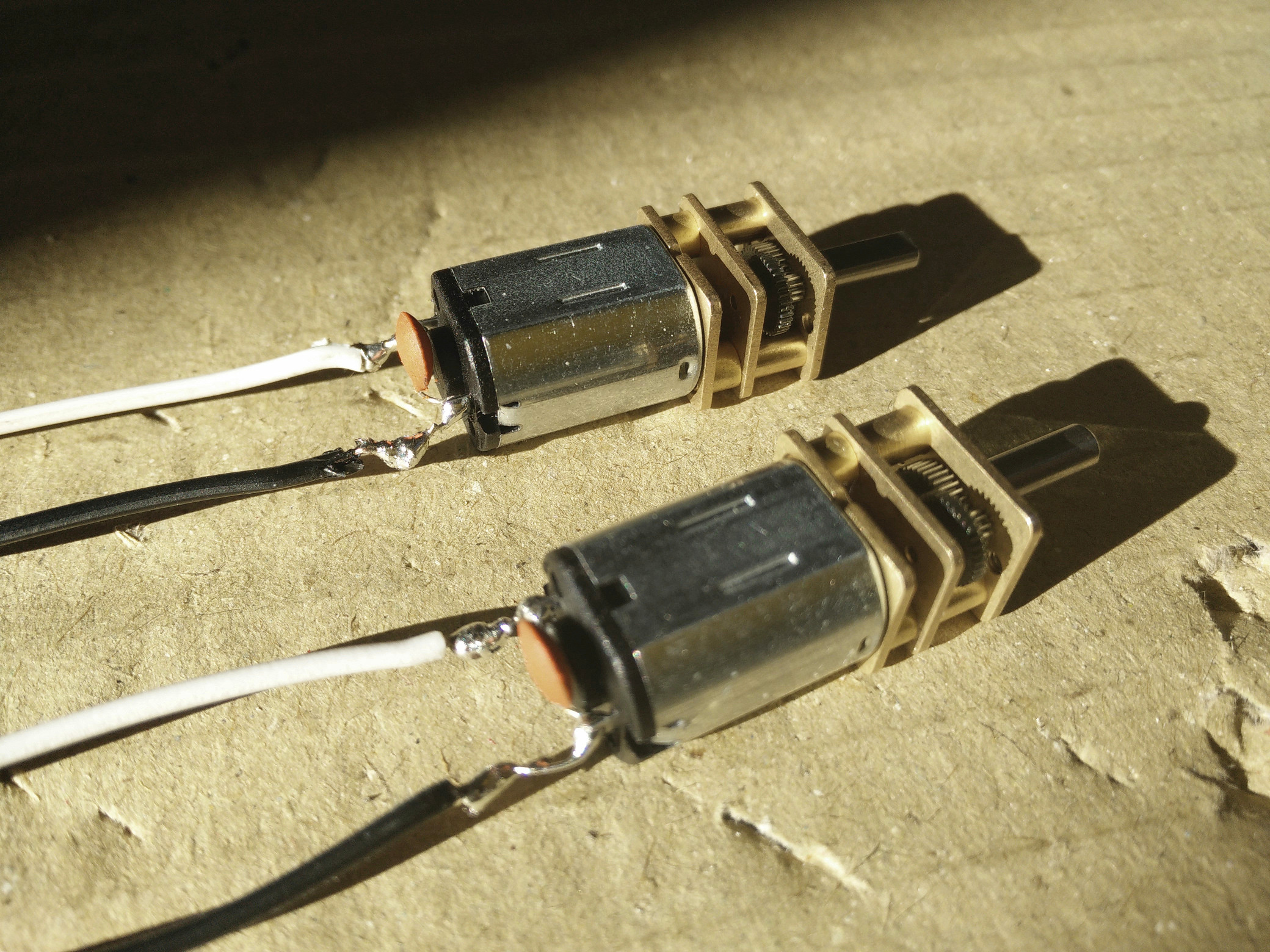
The wires are soldered to the motors with added parallel capacitors
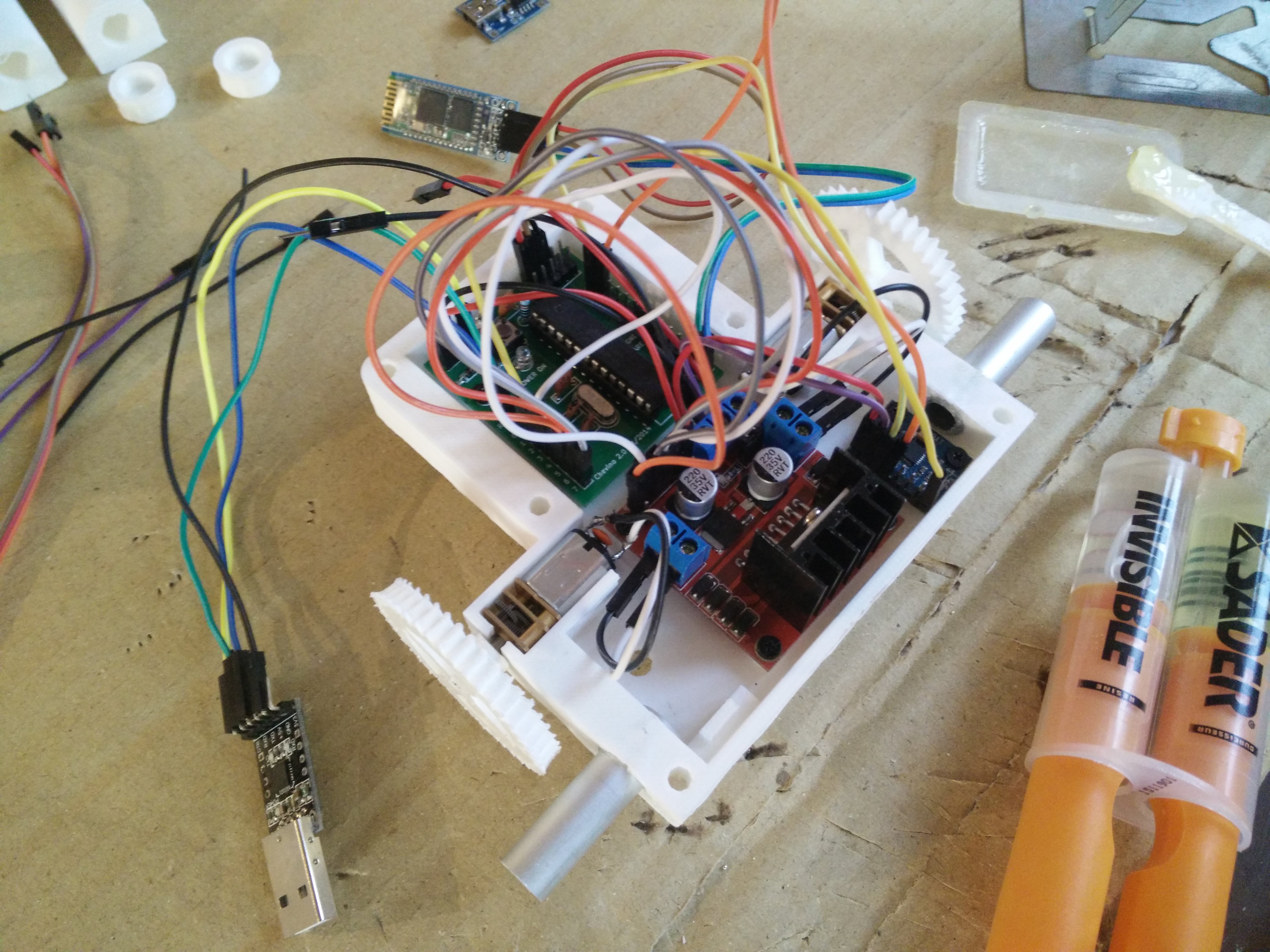
The motors are then clipped in the back frame and connected to the outputs of the L298N. They will be locked in place by the front frame. The MPU-6050 is fixed at the bottom left of the panel, to be on the axis of the wheels. The lipo charger can be clipped at the bottom right.
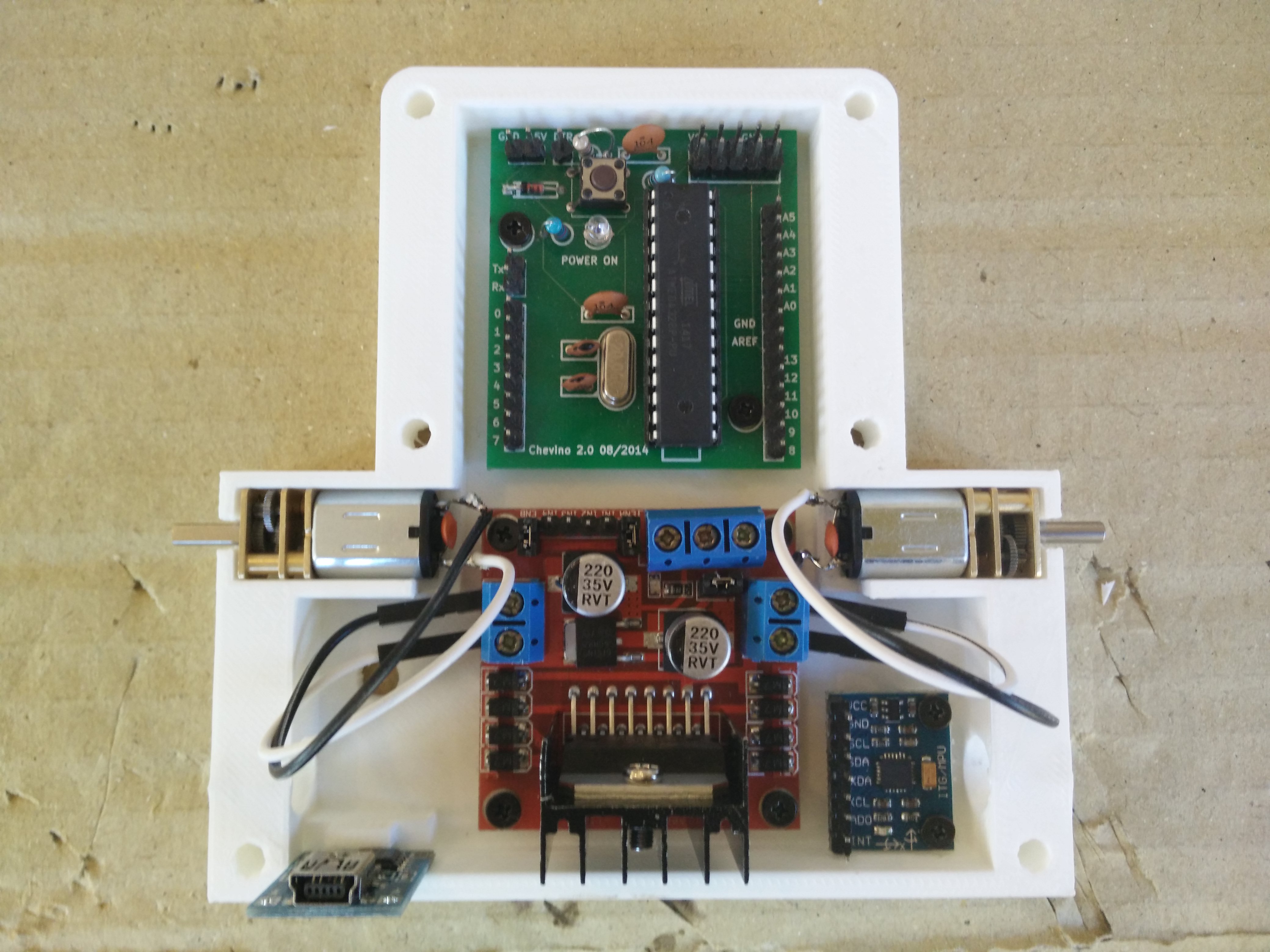
Components and motors placed in the back panel
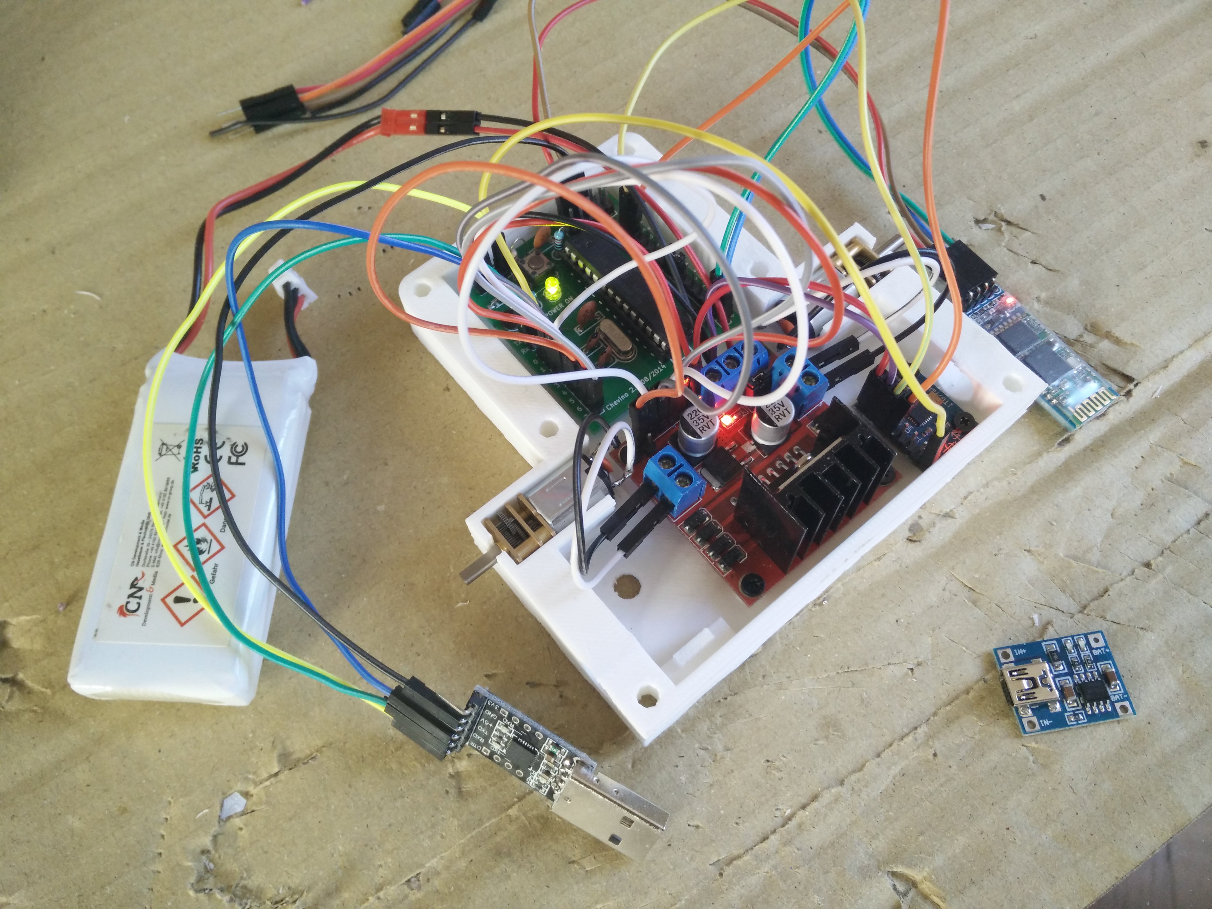
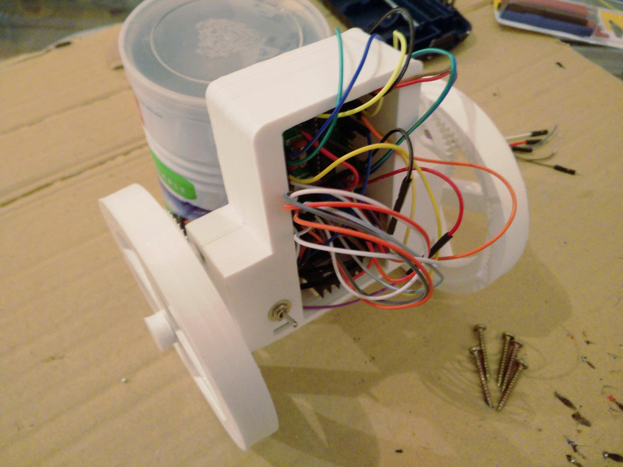
It's time to connect everything, mostly with Dupont wires. The Chevino, HC-06 and MPU-6050 are connected to the ground and the 5V output from the L298N. Two serials are connected to the Chevino, one for programming on the Tx, Rx and DTR pins and one for the HC-06 on pins 8 and 9. The MPU-6050 I2C pins are connected to the pins A4 and A5 of the Chevino, and the interrupt pin to pin 1. Finally, motor control uses pins 2 to 7, with pins 5 and 6 in PWM mode to control speed.
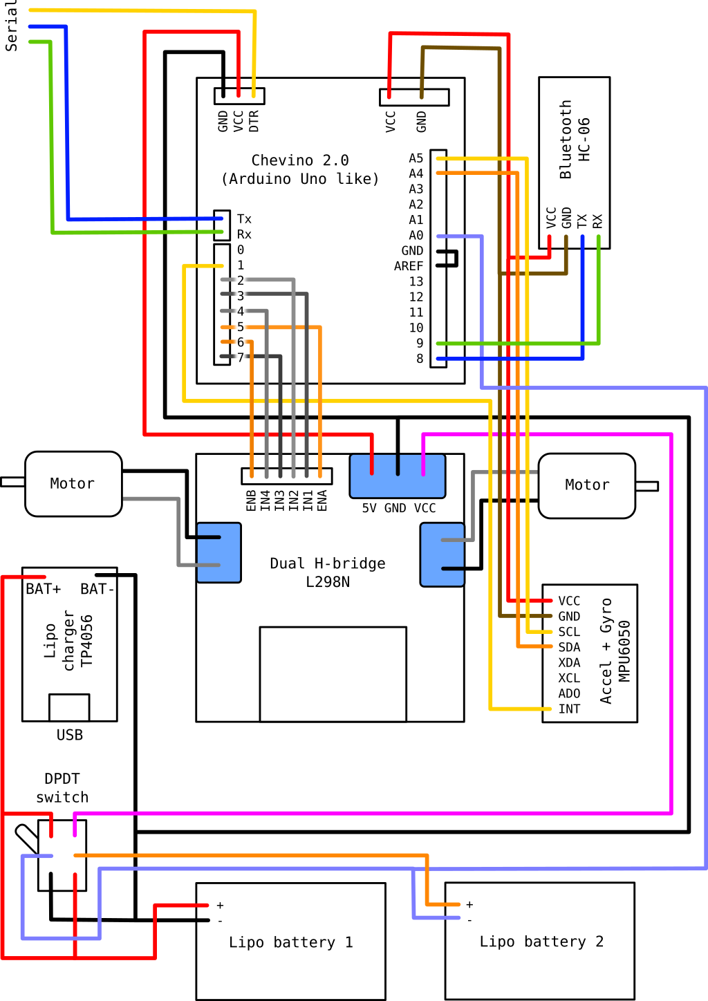
Schematic of the connections between components
The DPDT switch allows to switch between ON mode and charge mode, simply changing where the second battery is connected:
- In ON mode, batteries are connected in series and provide a 7.4V nominal voltage (actually up to 8.4V at full charge) to the L298N.
- In charge mode, batteries are connected in parallel to the lipo charger, in order to charge them via USB in a balanced manner.
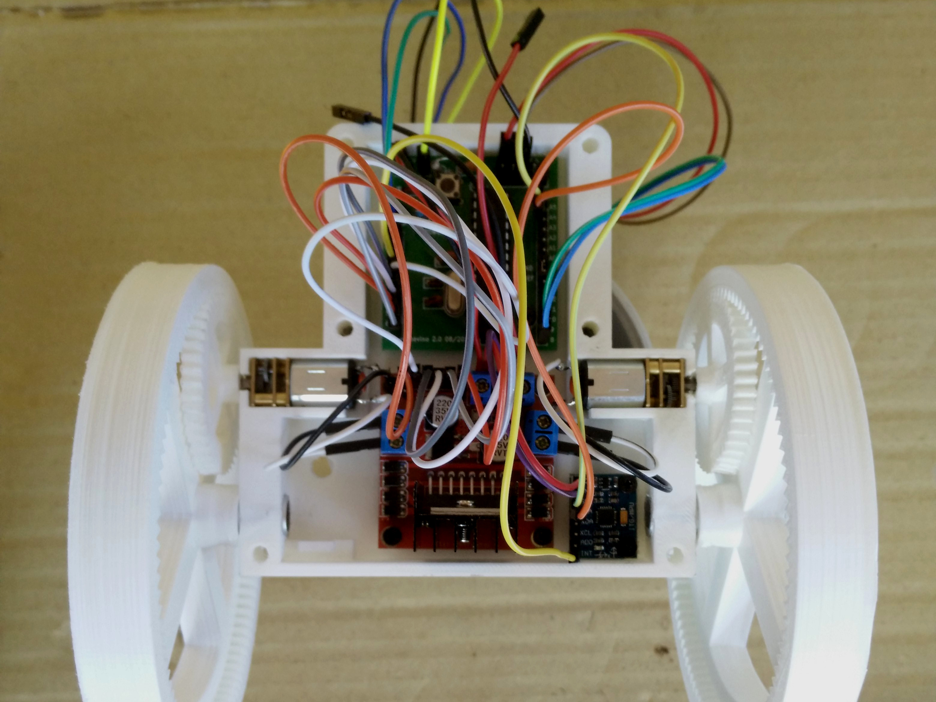
A probe is connected from the first battery to the A0 pin of the Chevino to measure the battery voltage and approximately deduce the charge left to the robot. In particular, this will prevent damaging the batteries by allowing the battery voltage to drop under 3.2V while the robot is running.
Most components are connected, testing power with a 2S lipo battery
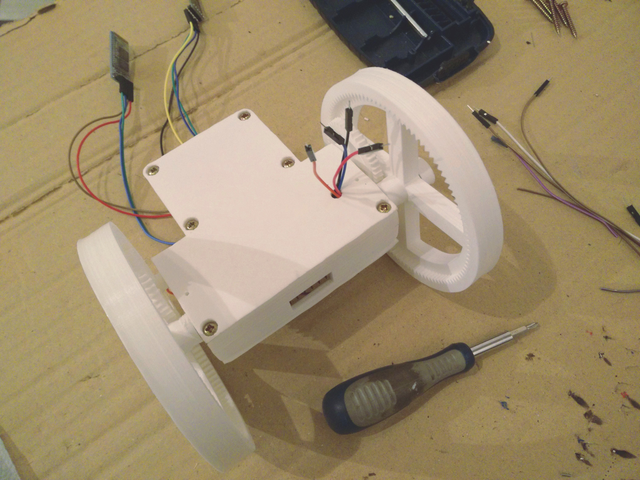
The wheels are not directly on motors axes but rather rotating on aluminium-tube axes and driven by internal gears connected to the motors. This design is way more robust, as the robot will be quite heavy, and it also allows to reduce speed (to roughly 60RPM) and increase torque.
Axes and gears for the wheels are glued to the frame
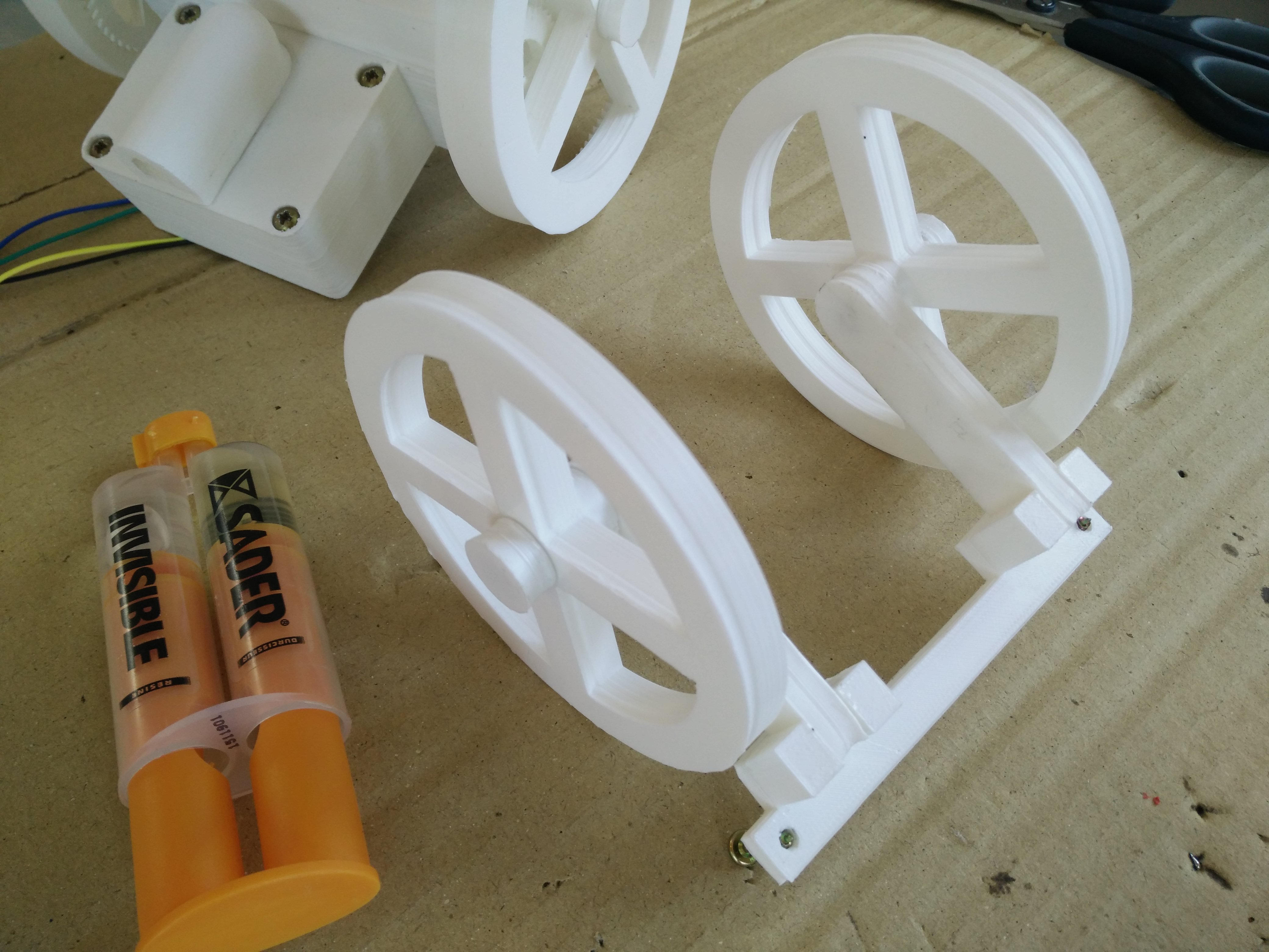
Gears are forced on the motors axes (with a bit of help from a soldering iron). Everything is glued with epoxy glue, then wheels are fitted on their axes and caps at the extremity are glued too. A few drops of vaseline oil help everything rotate smoothly.
Wheels are in place and tightened on the axes with caps
The last parts to add before closing the frame with the front part are the switch and the USB charger. A bit of soldering is required to connect the proper wires to the switch.
The switch is soldered and ready to be connected
Once the switch is attached to the front panel, the charger is in place, and everything is connected according to the schematic, we can close the frame. The four battery wires (with male connectors) need to go out on the back through the hole in the back panel.
The switch is attached to the front panel, the charger is clipped and the frame is closed
I designed the panels so they can be fastened together with six 3.5x30mm wood screws. Not the exact use for which they where intended, but it works perfectly! The battery compartment is also fastened to the body with two of the same screws, after the batteries are properly connected. You have to pay attention when connecting the batteries, a mistake could create a short circuit which would burn the cables - in the best case...
The front panel is screwed to the back panel
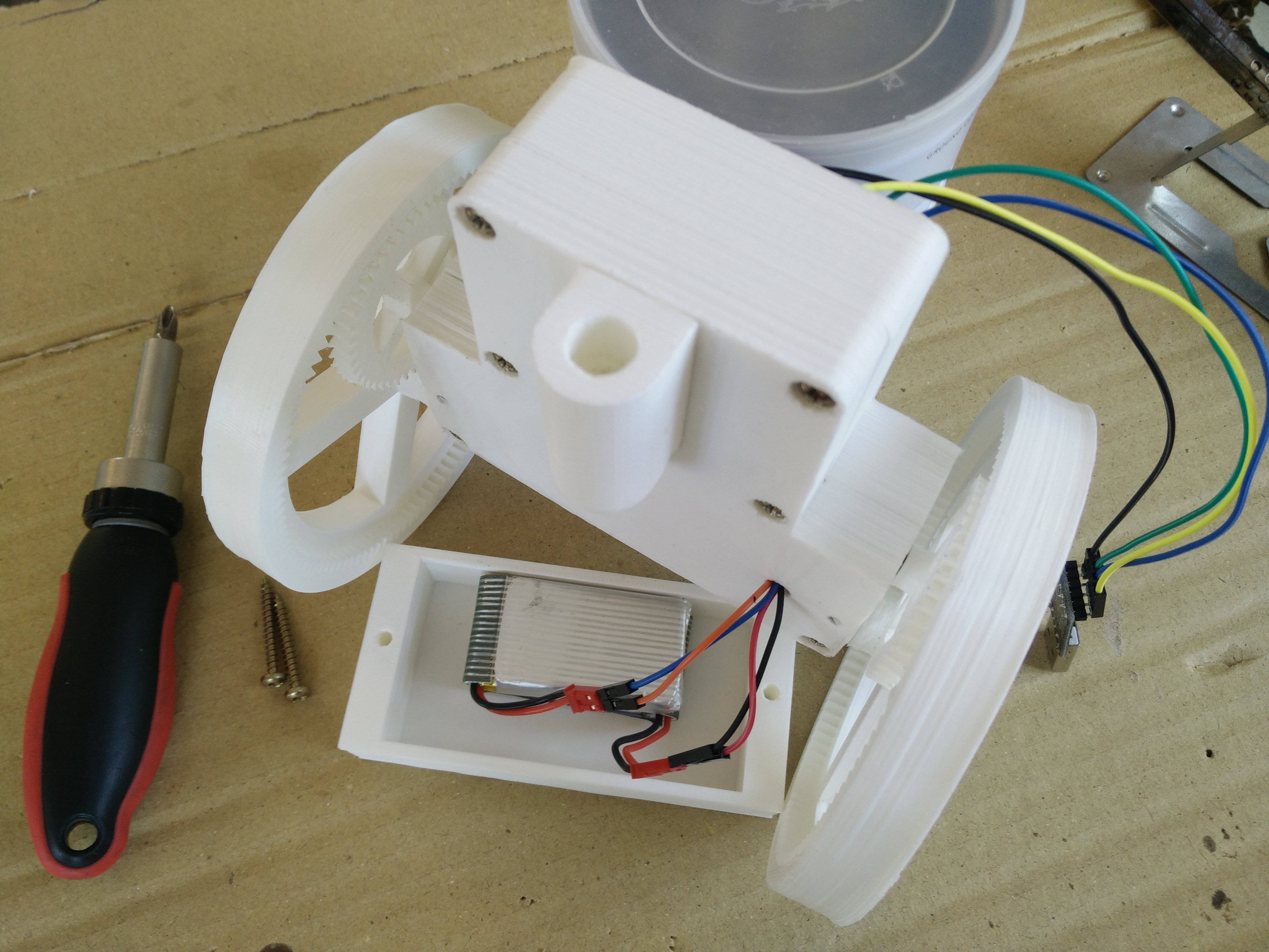
Batteries put inside their compartment
Then the connector for the pole is strongly glued to the frame with epoxy glue. The pole will have another connector on top to stick the smartphone. The back wheels are mounted on a back support that is then fixed with two smaller 3.5x20mm wood screws on the bottom of the battery compartment. Since the screws stay easily accessible, this design enables to easily dismantle everything even after the back wheels caps are glued.
The back support glued with back wheels attached
To get better adherence on the floor, I added two rubber bands per wheel as a form of somewhat primitive tires.
The base finished, with its closing lid clipped
Last but not least, we insert the pole with the smartphone sticked on the top connector with heavy-duty sticky tack. I've chosen a Motorola Moto G 3 running Cyanogenmod, but any Android smartphone with a good front camera would work. It's also good to add a protective cover to the smartphone, who knows what could happen during debugging?
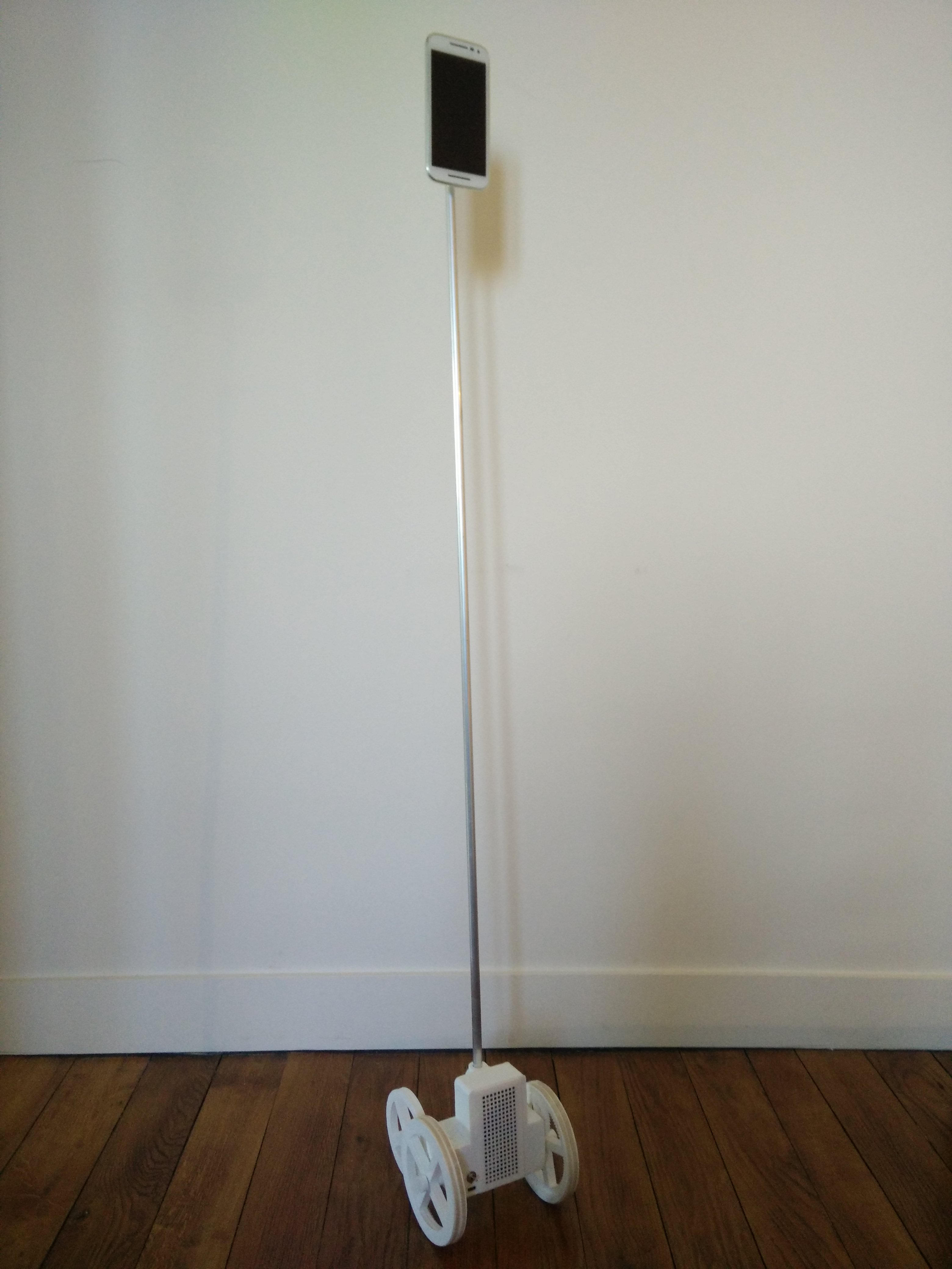
The Telebot is finished!
Now, the next step is of course to program the robot! Please refer to the next article.

